Legacy Simulation 
![]()
![]()
Access: Open this function from the following location:
Select Analysis > Motion Simulation > Motion Simulation & Groups - Load from the menu bar.
Then select the Legacy Simulations button.
Run a legacy simulation saved using the (pre-Cimatron 12.0) legacy motion simulation function - Motion Analysis.
Note: A brief description of the legacy motion simulation function (Motion Analysis) is shown below. For a complete description, see the Help for a pre-Cimatron 12.0 version.
The Load Motion Analysis Task dialog is displayed, enabling you to load existing legacy simulation runs.
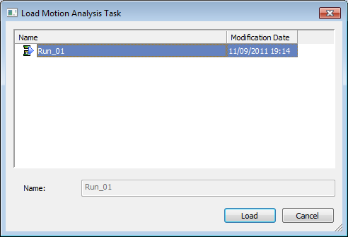
Select an existing simulation run and click Load. The Motion Analysis dialog appears as shown below:
The Motion Analysis dialog includes all tools and steps required for motion simulation and analysis. The dialog is divided into 3 areas:
Rigid Sets Tree - Groups of components that are fastened to each other in such a way that no relative movement can exist between members of the same rigid set. Components included in a rigid set need not be members of the same sub-assembly. Components can be assigned to the same rigid set regardless of their hierarchic position in the assembly tree.
The default colors of the rigid sets are defined in the Preferences. You can also define the colors locally in the rigid sets tree (overrides assembly tree definitions). The render mode of the components is derived from the assembly tree.
Motions Grid - Tracks the sequence of motions in timeline or sequential mode.
Tabs - Each tab contains the tools required for each stage of motion analysis. You can switch between stages by clicking the appropriate tabs:
Prepare Assembly
Set Motions
Simulate.
Prepare Assembly Tab
In this tab, the calculation of motion simulation can be optimized by using the following optional tools:
- Set Permanent Connections - Define permanent connections between entities that are constantly engaged, thus eliminating the need for creating some temporary connection.
- Set Colliding Components - Unselect parts that are insignificant in terms of collision detection analysis, and create temporary constraints.
- Edit Springs - Edit spring data (spring data is used when analyzing the assembly movements).
In addition, you can check for initial collisions - if interference already exists among components assigned to different rigid sets.
The following tab options are displayed:
Set Motions Tab
Motions are determined in the Set Motions tab. The direction and distance of motions are determined either by screen or dialog interaction (or both). There are 2 modes of motion definitions Timeline mode and Sequential mode. The contents of the Set Motions tab changes according to the mode selected when the legacy simulation was defined.
Timeline mode - A number of moving rigid sets can be defined along a timeline, where motions can overlap each other. This is the default mode.
Sequential mode - Motions are executed in sequential order, such that a new motion cannot start until the previous one is finished. Operation order and motions that partially overlap each other cannot be defined.
Simulate Tab
To run the simulation process, complete the parameters and then click the Calculate button to start the calculation process. Before actually running the calculating process, it is recommended to run a pre-calculation test: Check Data Validity.
After each calculation step, the display will update according to calculation results.
The controls in the Simulate tab differ slightly for Timeline and Sequential modes (timeline mode shown below):