|
|
Max. Inclination Angle
This is the maximum gap allowed between the selected geometries, when joining them into a single geometry. If the gap between the selected geometries is greater than the Max. Gap value, they are treated as separate geometries.
This parameter has the following uses:
-
To consider the maximum inclination that can be achieved by the rotary axis of the machine.
-
To remove from the selectable holes those holes that cannot be drilled since they are located at the bottom and the table prevents these holes from being drilled.
-
To enable a Through Hole to be drilled from both sides. If the angle is set such that a through hole can be drilled from both sides, then the Opposite Direction option is available in the Automated Drill Tool Trajectory Table.
Note: The default value of this parameter is 90 degrees. This has the following effects:
-
Only blind holes or enlarging through holes which open towards the upper hemisphere (according to the + Z axis) will be selectable.
-
For through holes, switching the drilling direction is prevented if the opposite direction points to the lower hemisphere. To enable this switching, increase the Max. Inclination Angle appropriately.
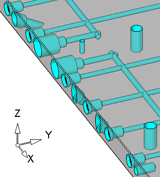
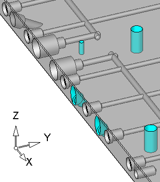
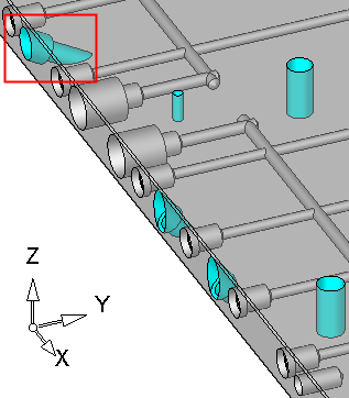
For example:
|
Max. Inclination Angle = 90: |
Max. Inclination Angle = 50: |
|
|
|
|
Max. Inclination Angle = 65: |
|
|
|
This parameter only appears in the Drill parameter table for the Automated Drill 5X procedure.
|


