|
|
Drill  > Automated Drill
  3X,
3X,  4X,
4X,  5X
5X
![]()
![]()
Access: Open this function from the following location:
-
For Technology, choose Drill as the main selection and Automated Drill as the subselection.
-
Select 3X, 4X, or 5X.
The Automated Drill is an advanced drill programming application that supports 2.5 to 5-axis manufacturing as well as Thread Milling, Gun Drilling, Pockets, and Profiles.
The application recognizes and sorts hundreds of holes in only seconds and automatically assigns the appropriate drilling sequence for each hole. The application's unique stock recognition capabilities take into consideration the stock existing above the hole before it is drilled. It then assigns the appropriate drilling sequence for such holes. This is useful in places where drilling is performed before the milling operation is complete and results in unprecedented time saving and elimination of user errors.
The entire model is scanned for holes; however, only the holes relevant to the current procedure are available for selection. This is dependent upon the type of drill procedure (3, 4, or 5-axis) and the Z direction of the active UCS. In addition, the limiting factor for 3X is Enlarging Holes and for 5X is the Max. Inclination Angle.
|
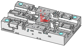
In this example for Automated Drill 3X, note the active UCS and the displayed holes. |
In this example for Automated Drill 5X, note the active UCS and the displayed holes. |
|
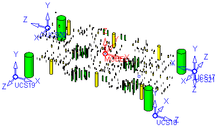
The same part with the Other Faces hiddenhidden. Note that all the scanned holes are displayed.
|
The same part with the Other Faces hiddenhidden. Note that all the scanned holes are displayed.
|
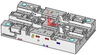
Of the holes relevant to the current procedure, the Free Through (opposite) Holes are initially hidden, as these holesthese holes can be drilled from either side.
|
|
|
Cimatron's Automated Drill is an adaptive system offering a user friendly interface to define any drilling sequence on-the-fly. The user-defined drilling sequences are automatically saved in the system for future use on similar holes, saving hours of programming time.
In addition, you can also add Constraints and Conditions in the drilling sequence where a particular process within a sequence can be activated according to the geometry of the specific Hole Group.
While the procedure is opening, the following occurs:
The entire model is scanned for holes regardless of whether the holes are displayed or not.
The Group and Sequence Manager is displayed to view the data that is of interest.
The Automated Drill Guide is displayed. This guide lists the Automated Drill steps in a logical order to guide you through the automated drilling process, from start to finish.
All the default Drill parameters are loaded into the parameters table.
An optimization is done to minimize the tool changes. The procedure stores all the data for the next edit.
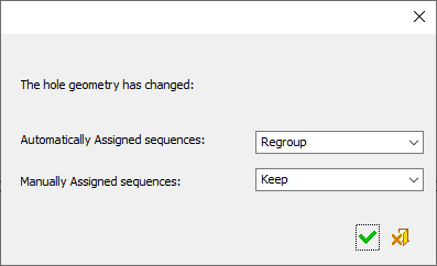
The stock or geometry are checked for changes since the last save operation. If changes have occurred, options are displayed to define the required action for automatically and manually assigned sequences (see below).
Automated Drill: Stock or geometry changes
If a stock or geometry change has occurred since the last save operation, the following options are displayed to regroup the automatically and manually defined sequences.
When the default options are selected, the holes are recalculated and the system checks that the existing holes are still valid. The Groups remain with the same Holes and the Sequences remain attached to the Groups.
Automatically Assigned sequences
Set the option for automatically assigned sequences, from the dropdown list. The following options are available:
|
Regroup |
Regroup automatically assigned sequences: The following regroup operation occurs: A new group is created for each sequence that contains non-empty groups. Each new group is checked to see if it still matches the sequence definition. If not, it is moved to the Unassigned Groups. A new group is created for all grouped holes in the Unassigned Groups list. All empty groups are deleted. Note: Point Selected Drills are lost. |
|
Keep |
Keep the currently assigned sequences. Some sequences may not fit. |
|
Remove Modified |
All changed holes are removed from their groups. |
Manually Assigned sequences
Set the option for manually assigned sequences from the dropdown list. The following options are available:
|
Keep |
Keep the currently assigned sequences. Some sequences may not fit. This is the default option. |
|
Remove Modified |
All changed holes are removed from their groups. |
When finished, press one of the following approval options:
|
|
OK: Accept the changes, perform the operation, and close the current dialog/task. |
|
|
Cancel: Cancel all changes and close the dialog/task without saving the settings. |
Notes:
-
The faces that make up each hole have to be stitched.
-
When an Automated Drill procedure is divided by a Cutter Change, the comment of the created procedure contains the sequence name.
The <Sequence Name> is defined as follows: If all motions in the created procedure belong to a single sequence, then it is the name of that sequence, otherwise the name is Multi Sequence.
The format of the comment is as follows: <Sequence Name> N of M <old procedure's comment>.
For example:
Single sequence: Through 16 H=27 9 of 14 No Text
Multi sequence: Multi Sequence 7 of 14 No Text
For specific information regarding Automated Drill, see the following:
Group and Sequence Manager (Tree)
Automated Drill Parameters (Tool Trajectory)
Creating this procedure
(See Creating a Procedure for a general explanation.)
For Technology, choose Drill as the main selection and Automated Drill as the subselection.
Choose 3X, 4X, or 5X.
View the Automatic Drill Cutters List.
The Automated Drill Guide is displayed. This guide lists the Automated Drill steps in a logical order to guide you through the automated drilling process, from start to finish. Here you define groups of holes and attach drilling sequences to them.
Define the Geometry (Part Surfaces and Check Surfaces).
Define the following Motion Parameters:
-
Tool Trajectory (this branch is not initially displayed and only appears once a drilling sequence has been created, and if the Cutter Sequence Data table has at least one entry)
Define the Machine Parameters.
When finished, you can choose from the following Work Mode Dialog buttons:
(These options are also available on the Procedure popup submenu.)
|