|
|
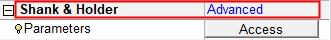
Shank and Holder Usage Dialog: Collapsed
![]()
![]()
Access: Open this function from the following location:
-
Click the Access button in the Shank and Holder Advanced branch of the Motion Parameters table.
This displays the Shank and Holder Usage dialog.
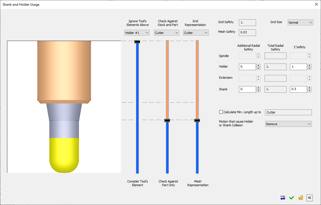
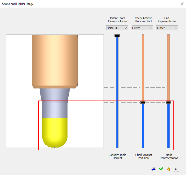
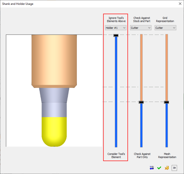
The Shank and Holder Usage dialog displays the default shank and holder parameter settings and enables you to adjust the parameters as required. A graphical interface and slider controls assist in explaining the parameters.
The Shank and Holder Usage dialog is initially displayed in collapsed mode, without showing parameter settings. This part of the dialog controls the shank and holder usage and defines which parts of the tool are considered or ignored for procedure collision check calculations.
|
|
Use the Expand See Expanded for dialog items specific to this mode. Collapsed dialog Elements: |

The dialog can be expanded to the right. The left side of the dialog controls the shank and holder usage (for procedure collision check calculations) and the right (expanded) side of the dialog deals with safety margin values, minimal clear length, and how the system deals with colliding motions.
Expanded DialogExpanded Dialog - See Expanded for dialog items specific to this mode.
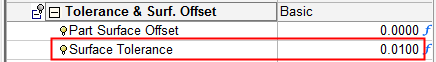
The cutter is always checked against accurate part as defined by the
surface tolerance in the table parameters.
The availability of sliders and/or parameters in the Shank and Holder Usage dialog is procedure-dependent. The dialog images above show a general case for Finish procedures with a single cutter and no tilting. See Procedure-Dependent Shank and Holder Usage dialog for additional examples of the dialog.
Sliders
Sliders are used to control the shank and holder usage; whether they are considered or ignored for procedure collision check calculations.
General Information on Sliders Used in CimatronGeneral Information on Sliders Used in Cimatron
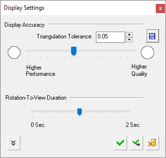
Sliders are used throughout Cimatron to enable users to make selections from a range of values; for example, for selecting the transparency level of selected objects or for selecting the required display settings. Sliders reflect the current state of the settings that they control. They may be displayed vertically or horizontally.
A slider may contain the following elements:
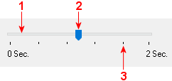
Track: The slider track shows the range of available values.
Handle: The slider handle slides along the track to a selected position (value).
Tick Marks: These represent values along the slider track.
|
Sliders may have icons or values at each end of the track to reflect the results. Slider values may be controlled by either sliding the handle along the track or by entering a value in a numeric field. Where a numeric field is associated with a slider, a change in one affects the other (for example, the slider handle position is updated to reflect any change in the numeric value and vice versa). All these cases (icons/values at each end of the slider track and an associated numeric field) appear in the Display Settings dialog, shown on the right.
|
|
Slider Track Colors
|
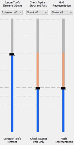
In the Shank and Holder Usage dialog, the slider tracks are color-coded to denote a certain status, depending on the slider.
The left slider track is colored BLUE below the slider handle and GRAY above the handle. The second and third slider tracks are colored BLUE below the slider handle and may have ORANGE and/or GRAY above the handle. The slider track colors denote the following cases: Active slider = BLUE (below the slider handle) and ORANGE (above the handle). Locked slider = GRAY. Irrelevant slider = GRAY with no slider handle. In general, all tool elements above the slider handle refer to the text above the relevant slider, and all tool elements below the slider handle refer to the text at the bottom of the slider. This is shown below, see: |
|
|
|
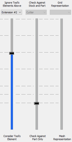
Active sliders |
The left slider is active, the middle slider is locked and the right slider is irrelevant |
Slider Handle Positions
The possible locations of each slider handle are inter-related as detailed below:
The second slider handle (Check Against Stock and Part) cannot be above the first slider handle (Ignore Tool's Elements Above), because it cannot refer to tool elements that are ignored by the first slider.
The third slider handle (Grid/Mesh Representation) cannot be above the first slider handle (Ignore Tool's Elements Above). It cannot be below the second slider handle, if the second slider is activated.
Cutter Check
The cutter is always checked against accurate part as defined by the
surface tolerance in the table parameters.
Ignore Tool's Elements Above
This slider bar indicates that all elements above the slider handle will be ignored in the procedure collision check calculations.
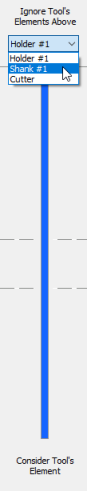
In the example below, all the elements will be included, as there are no elements above Holder#1. Ignore Tools Elements Above Holder#1:
To change which tool elements are included or ignored in the calculations, either drag the slider handle towards another tool element level (denoted by a dashed line across the slider bar) or use the dropdown list to select the required tool element. Anything above the selected tool element will be ignored in the calculations.
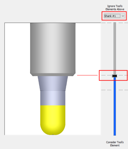
| In the examples below, Shank #1 is selected from the dropdown list and the slider handle position is updated to reflect the change. Note that the holder element turns gray; this means that it will be ignored in the calculation. | |
|
|
|
Check against Part Only/ Check Against Stock and Part
This slider bar enables you to define which part of the tool (Shank, holder, spindle elements) are checked against the part surfaces only, and which elements are checked against part and stock, in the procedure collision check calculations.
The BLUE part of the slider track refers to the Check Against Part Only option, while the ORANGE part refers to Check Against Stock and Part. The cutter, of course, cannot be checked against stock.
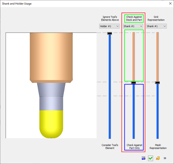
In the above example, Shank #1 is selected from the dropdown list, so the cutter and shank will be checked against the Part only, and the rest of the tool elements above the shank (in this case only Holder#1) will be checked against the Stock and Part.
For additional information, see Check Against Part/Stock.
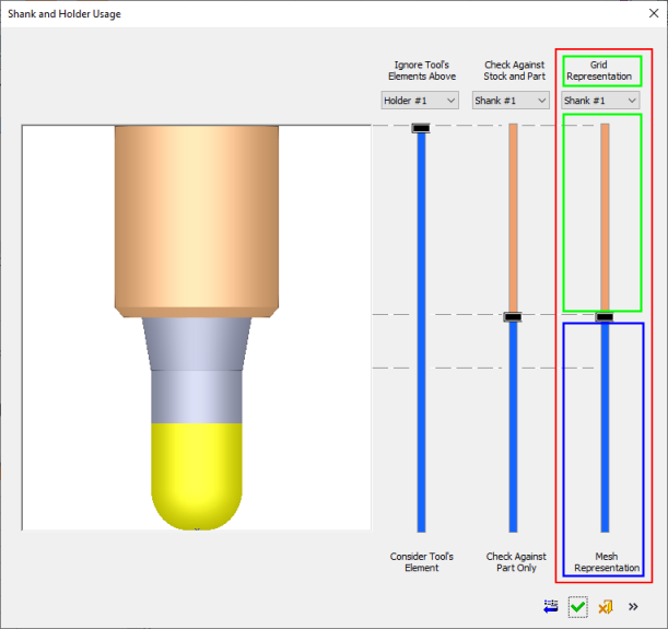
Grid/Mesh Representation
This slider bar enables you to check accuracy.
Elements above the slider handle (colored ORANGE) are checked against the grid representation of stock and part.
Elements below the slider handle (colored BLUE) are checked against the mesh representation of stock and part.
|
|
All elements that are Check Against Part Only are always checked against Mesh Representation of the part. |
The cutter is always checked against accurate part as defined by the
surface tolerance in the table parameters.
|