|
|
Shank and Holder Usage Dialog: Expanded

Access: Open this function from the following location:
-
Click the Access button in the Shank and Holder Advanced branch of the Motion Parameters table.
This displays the Shank and Holder Usage dialog.
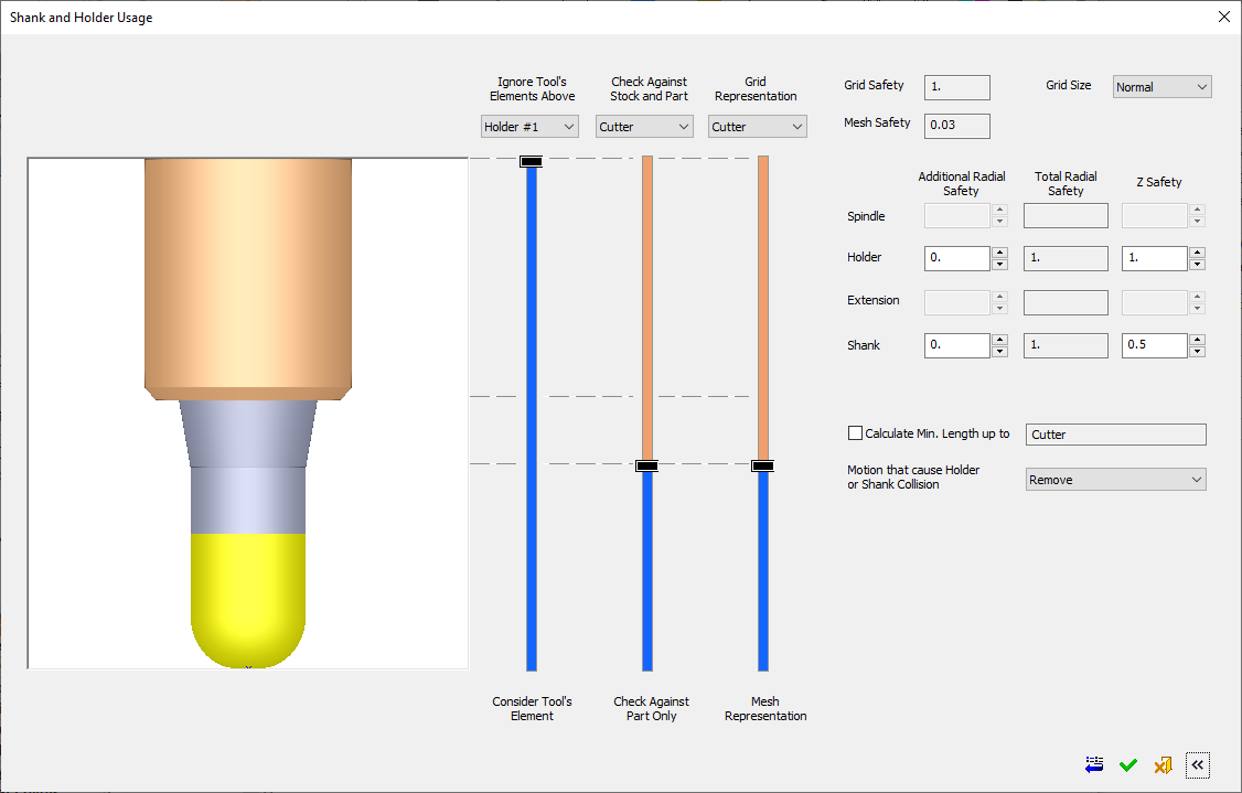
The Shank and Holder Usage dialog displays the default shank and holder parameter settings and enables you to adjust the parameters as required. A graphical interface and slider controls assist in explaining the parameters.
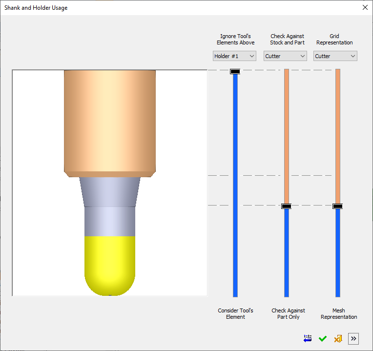
The dialog can be expanded to the right. The left side of the dialog controls the shank and holder usage (for procedure collision check calculations) and the right (expanded) side of the dialog deals with safety margin values, minimal clear length, and how the system deals with colliding motions.
Collapsed DialogCollapsed Dialog - See Collapsed for dialog items specific to this mode.
The availability of sliders and/or parameters in the Shank and Holder Usage dialog is procedure-dependent. The dialog images above show a general case for Finish procedures with a single cutter and no tilting. See Procedure-Dependent Shank and Holder Usage dialog for additional examples of the dialog.
Shank and Holder Usage Dialog Parameters
|
Grid Safety |
Grid Safety displays the basic minimum safety distance and is not directly controlled by the user. You can influence the grid safety factor by controlling the Grid Size (adjacent parameter). |
|
||||
|---|---|---|---|---|---|---|
|
Grid Size |
Set the grid size from a dropdown list of options: Default = Normal. This parameter is not displayed if the Grid/Mesh Representation slider is locked to the top or not relevant (gray with no slider handle). |
|||||
|
Mesh Safety |
Mesh Safety displays the basic minimum safety distance and is not directly controlled by the user. |
|||||
|
|
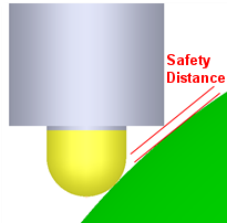
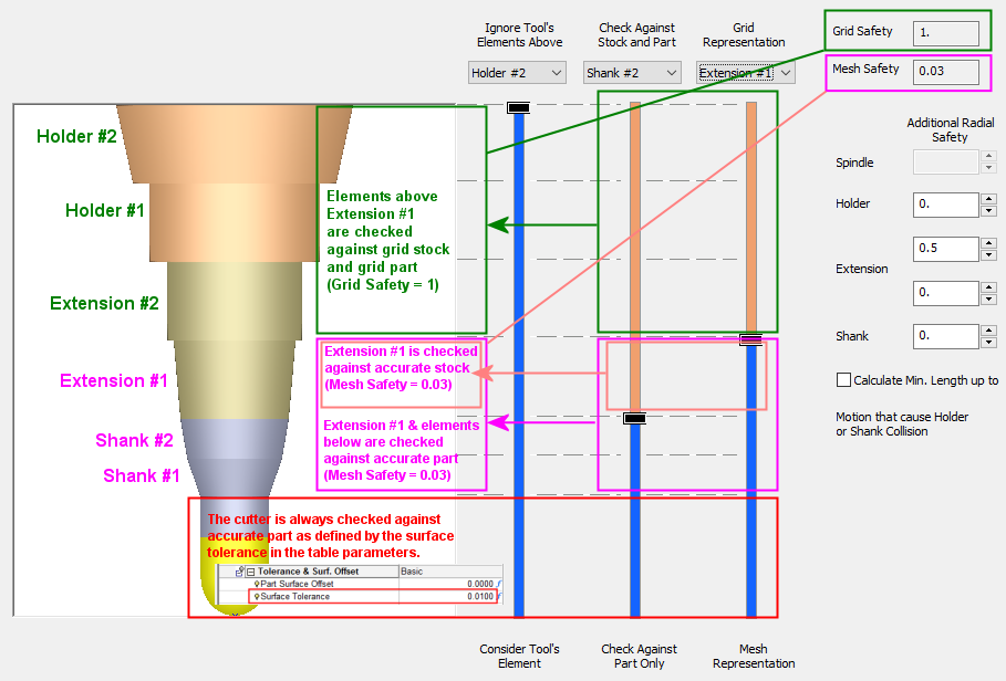
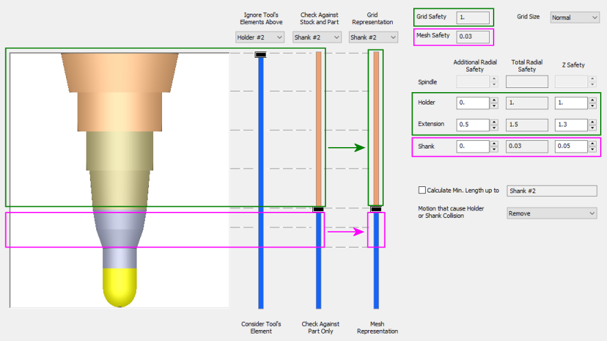
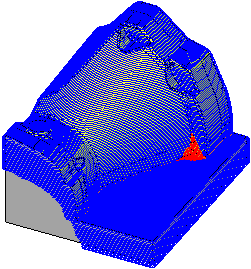
Example of which tool elements are checked against grid stock and part (Grid Safety) and which are checked against accurate part (Mesh Safety):Example of which tool elements are checked against grid stock and part (Grid Safety) and which are checked against accurate part (Mesh Safety):
The lower red rectangle: The cutter is always checked against the part, according to the surface tolerance defined in the parameters table. The magenta rectangle: Extension#1 is checked against both stock and part with an accuracy of mesh safety value. Mesh Safety =0.03. Shank#2 and Shank#1 are checked against part only with an accuracy of mesh safety value. Mesh Safety =0.03. The upper green rectangle: Elements above Extension#1, which are in our case: Extension#2, Holder#1, Holder#2 are checked against both stock and part with an accuracy of grid safety value. Grid Safety =1. |
|||||
|
Safety Parameters |
Safety parameters are displayed for each of the tool elements above the Cutter (Shank, Extension, Holder, Spindle). The toolpath will not get closer than the Total Radial Safety and Z Safety values. |
|||||
|
Additional Radial Safety |
Additional Radial Safety (#1) is any additional grid (or accurate) radial safety margin you may add to the default (Grid/Mesh) safety margin values. Defaults: |
|
||||
|
Total Radial Safety |
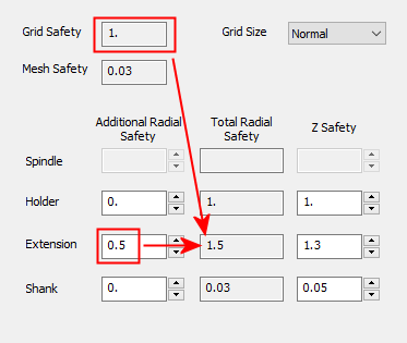
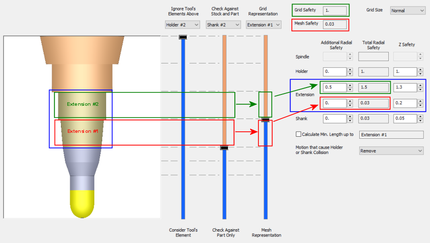
Total Radial Safety (#2) is derived from both the additional value and the Grid/Mesh Safety value. Elements that are checked against grid representation get the Grid Safety value and elements that are checked against accurate stock get the Mesh Safety value. In the example below, the Additional Radial Safety for the Extension is set to 0.5. The Total Radial Safety is updated to 1.5 = (Grid Safety) 1 + Additional Radial Safety 0.5. In this case, the Z Safety was manually changed to 1.3.
|
|||||
|
Z Safety |
Z Safety is the axial safety margin value along the Z direction. Defaults: |
|||||
|
|
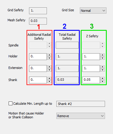
All elements that are checked against Grid representation of stock and part get a basic Radial Safety (Grid Safety) of 1. In the example below, all elements that are checked against Grid representation of stock and part (in this example, Extensions and Holders) get a basic Radial Safety (Grid Safety) of 1. The basic Radial safety of the Extension in this case is 1 (Grid Safety).
Total Holders Safety = 0 (Additional) +1 (Grid Safety) = 1, Z Safety = 1 Total Extensions Safety = 0.5 (Additional) +1 (Grid Safety) = 1.5, Z Safety = 1.3 All elements that are checked against Mesh representation of stock and part, get a basic Radial safety (Mesh Safety) of 0.03. The basic Radial safety of the Shank in this case is 0.03 (Mesh Safety).
Total Shank Safety = 0 (Additional) +0.03 (Mesh Safety) = 0.03, Z Safety = 0.05.
If a tool element (Spindle, Holder, Extension or Shank) is split by the Grid/Mesh Representation slider, the Total Radial safety displays two values; however, each segment is calculated according to the grid or mesh it uses. In this example, the Extension is split by the Grid/Mesh Representation slider and each segment of the Extension is calculated according to the grid or mesh it uses.
|
|||||
|
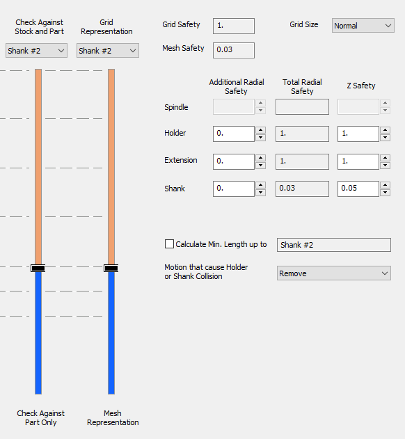
Calculate Minimum Length up to |
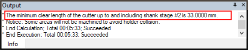
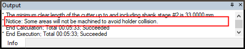
The Calculate Minimum Length up to parameter calculates the minimum tool length (up to the defined tool segment) that is required to complete the machining of an executed procedure, without leaving unmachined regions due to holder or shank collisions. For example, if the defined tool segment is Shank
#2 (as shown in the image below), then the minimum tool length
up to Shank #2 is calculated to enable machining of an executed procedure,
without leaving unmachined regions due to holder or shank collisions. The calculated information is displayed in the Output Pane and the NC Process Manager (in the Holder & Shank in Use column); Output Pane example:
Using this information, you can either adjust the tool length (a cutter with this calculated minimum length can then be used for the actual machining) or limit the toolpath depth to prevent the holder from colliding. A checkbox is displayed adjacent to the Calculate Minimum Length up to parameter. For additional information on minimum length, see Calculate Minimum Length. |
|
||||
|
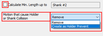
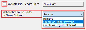
Motions that cause Holder or shank Collision |
This parameter highlights unmachined areas that were calculated but not yet machined due to the holder prevention mechanism (to avoid holder collision with the part/stock). This parameter tells the system what to do in the case of motions that cause holder or shank collisions. A dropdown list of the following options is available. The options that are actually available from the dropdown list depend on the status of the Calculate Minimum Length up to checkbox parameter.
|
|||||
|
Remove |
Motions that cause holder or shank collisions are removed. Besides the visual indication that motions causing holder or shank collisions are removed, there is no further indication that this has occurred. For additional information, see Calculate Unmachined Areas. |
In the example below, the Finish motions did not cover all the faces that were selected for machining, due to holder collision prevention mechanism.
|
||||
|
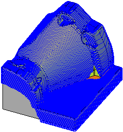
Create as Holder Prevent |
This parameter highlights unmachined areas that were calculated but not yet machined due to the holder prevention mechanism (to avoid holder collision with the part/stock). A message about areas not machined to avoid holder collision appears in the Output Pane as well as other places; for example: Information on these unmachined areas (Holder Prevented Areas) is displayed/controlled in additional locations, see Calculate Unmachined Areas. |
In the example below, the motions that would have been calculated if not prevented by the holder are clearly highlighted in the display. These are the areas that the current tool/holder cannot reach and are not machined.
|
||||
|
Create as Regular Motions! |
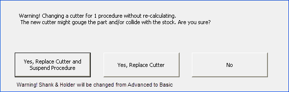
Create all motions as regular motions, taking into account that the cutter will be later replaced as recommended. When this option is selected, on saving or executing the procedure, a warning message is displayed that the system may create motions that cause holder or shank collisions. This warning messages is also displayed when changing the cutter from the Process Manager or when editing the cutter in the Cutter Table in the relevant dialog.
For additional information on cutter changes and their affect on the status of the Shank & Holder parameter branch, see Cutter Changes and, for general cutter change information, see also Update Cutter (Without Suspending Procedure). |
|||||
|
|
||||||
|
|
||||||


|