Create a Part Procedure 
![]()
![]()
Access: Open this function from one of the following locations:
Select the toolpath for which the part will be created, then create the part in one of the following ways:
-
Select NC Process > Process > Part from the menu bar.
-
Click the Part button
from the NC Guide Toolbar.
Part is a 3X procedure used to represent the final-product designed part. Part is a special procedure that only contains faces; it does not contain any toolpaths.
The part procedure is used by the Machining Simulation for comparing actual milling results to the desired product.
Creating a Part
A toolpath must be created first. See Creating a Toolpath for details.
-
UseUse the Part function.
-
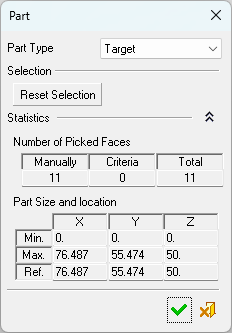
The Part dialog is displayed. On the Part dialog, choose the Part Type you are defining.
See below for the dialog parameter explanations.
-
Pick the surfaces to define the part. There are several ways to pick surfaces, including right-clicking and selecting one of the options in the upper section of the following popup submenu:
Note: To clear your selection, you can press the Reset Selection button (in the dialog) at any time.
-
As the surfaces are picked, various statistics are displayed in the dialog. If required, expand the dialog to view these statistics (see below for the dialog parameter explanations).
-
When you have finished, press one of the following approval options (these are also available in the right-click popup submenu shown above):
|
|
OK: Accept the changes, perform the operation, and close the current dialog/task. Save and close. |
|
|
Cancel: Cancel all changes and close the dialog/task without saving the settings. |
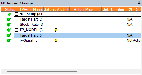
After the Part is saved (by clicking ![]() in the Part dialog), it will appear in the Process Manager with a
in the Part dialog), it will appear in the Process Manager with a  status flag and a name which reflects the part type (see below for the dialog parameter explanations):
Parameters
|
Part Type |
Define the type of the part procedure created.
Later, in simulations, each of these part types can be selected, individually or together, to define the part on which the simulation is to be performed. For example, a Fixture Part can be selected enabling you to check for possible collisions between the cutter and fixtures. |
||||||||||
|
Selection |
The Reset Selection button clears your picked faces and resets the Statistics section to zero. |
||||||||||
|
Statistics |
Based on the faces you have picked, this area displays the following data: Note: Press the Expand
|