Create Points on Skin  : Options and Results


Access: Open this function from one of the following locations:
Access: Open this function from the following location:
-
Select Die Design > Springback > Create Points on Skin from the menu bar.
-
Select Springback > Create Points on Skin from the following Die Design Guide: Die Process Design Guide (Forming).
-
Select Solid > Warp > Create Points on Skin from the menu bar.
Create points with a constant difference the points, ignoring areas with a small curvature. The points are created as a point cloud. These points can then be used in the Springback table of points.
Required Step 1 
-
Pick an object (B-rep or mesh) or faces on which the points are to be created. For example:
-
The parameters displayed depend on the method selected to spread the points (By Grid or By Triangulation).
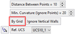

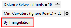
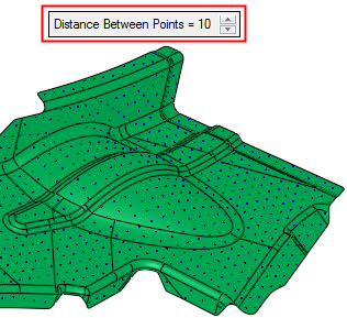
Distance Between Points
Set the distance between the created points.
Example:Example: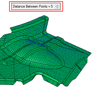
Min. Curvature (Ignore Points)
Set the minimum curvature of the skin for the creation of points. If the curvature anywhere in the skin is below the set minimum, points are not created on that section of the skin.
Example:Example: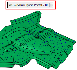

By Grid / By Triangulation
This is a toggle option By Grid / By Triangulation that defines how to spread the points.
By Grid
Spread the points in a grid, taking into account the other parameter settings.
Example:Example: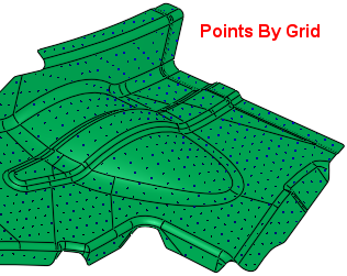
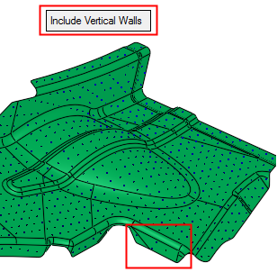
When this option is selected, an adjacent toggle option Ignore Vertical Walls / Include Vertical Walls enables you to ignore or include vertical walls when creating the points.
Example:Example: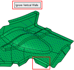
By Triangulation
Spread the points by triangulation. This re-facets the B-rep or mesh, taking into account the other parameter settings.
Example:Example: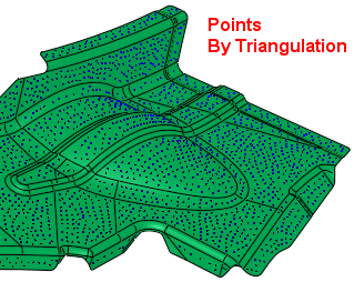
Ref. UCS
Select a reference UCS from the dropdown list of UCSs on the object; the default is the active UCS. The reference UCS defines how the distribution of points is calculated and where they are displayed; for example, the Z direction defines vertical walls and, depending on the parameter settings, may not have points on them - see below.
The
 button enables you to pick a reference UCS.
 - Click the Preview button on the Feature Guide to display a preview (and the number) of the calculated points, based on the parameter settings. The number of the calculated points is displayed in the Status Bar.
- Click OKOK
 or ApplyApply
 in the Feature Guide to complete the function.

-
When completed, the Create Points feature will appear in the Feature Tree as follows (the feature (points) are created as a point cloud):