Springback Deform  /Advanced Warping
  : Options and Results


Access: Open this function from one of the following locations:
Access: Open this function from the following location:
-
Select Die Design > Springback > Springback Deform from the menu bar.
-
Select Springback > Springback Deform from the following Die Design Guide: Die Process Design Guide (Forming).
-
Select Solid > Warp > Advanced Warping from the menu bar.
Note: The Springback Deform function is also available to users who do not require the Die application. In this case, it is called Advanced Warping and is nearly identical to the Springback Deform function (with the exception of some parameter names).
Advanced Warping Note: The availability of this function is license dependent; contact your Reseller for the appropriate license.
Often, sheet metal parts require over-bending to compensate for elasticity of the metal. Using a combination of professional experience and Finite Element Analysis (FEA) tools, you can determine the required over-bending extent, enabling you to model the forming shape as necessary.
This function uses springback data to compensate for springback during the tool development phase, to reduce expensive and time-consuming tryouts. This springback data is created either by a Finite Element application (by measuring after completing a test operation) or by using your die maker experience.
An example of this process is
|
1. |
2. |
|
|
|
|
|
|
3. |
4. |
5. |
|
|
|
|
Required Step 1 
- Pick the object upon which the springback operation is to be performed. For example:
The system automatically proceeds to the next required step.
Required Step 2 
- Optionally, pick fixed constraints (such as faces, edges, curves, sketches, composites, wire curves, or points) on the object.
- Click <exit><exit> to proceed to the next required step.
Required Step 3 
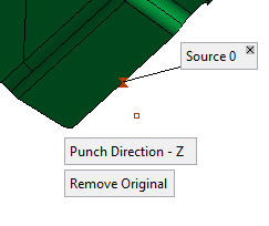
- Define coincident constraints and the punch direction. Pick pairs (source/target) of constraints and set the punch direction. These constraints can be edges, curves, sketches, composites, wire curves or points.
When a constraint is picked, a label is attached to the constraint identifying whether it is a source or target and showing the source/target pair number. When additional constraints are picked, the source/target pair numbers are both incremented by one to identify the pairs. For example:A source constraint is picked. An identifying label is displayed.
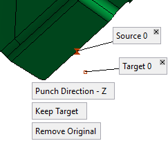
A target constraint is picked.
An additional label identifies the constraint and the identical source/target numbers signifies that these are a pair.Springback parameters:
Advanced Warping parameters:

Notes
-
The source and target constraints can only be of the same type. This means that if a point is picked as a source constraint, the target can only be a point, etc.
-
If a source constraint is deleted, then its corresponding target constraint is also deleted and the remaining source/target pair numbers are adjusted accordingly.
-
If a target constraint is deleted, then its corresponding source constraint is giving the last number and you are prompted to pick a new target for this source.
-
If a wire constraint is picked, it must be smooth.
The following parameters are displayed:
Punch Direction - Z
This is a toggle option that enables you to define the punch direction: Punch Direction - Z / Punch Direction - User-Defined.
Punch Direction - Z
Set the Z direction as the punch direction. This is the default option.
If the part is a die forming part, the option Work CS is displayed.
If the part is a non-forming part, the option Z - Direction is displayed.Punch Direction - User-Defined
This option enables you to define the tipping direction by using the displayed directional arrow.
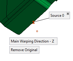
Note: In the Advanced Warping function, the Punch Direction parameters are renamed as Main Warping Direction, as shown below:
DieDesign > Springback Deform function
Solid > Warp > Advanced Warping function
Punch Direction – Work CS
Main Warping Direction – Work CS
Punch Direction – Z
Main Warping Direction – Z
Punch Direction – User-Defined
Main Warping Direction – User-Defined
Keep Target
This option is displayed once a target constraint had been picked.
This is a toggle option that enables you to either keep or reverse the direction of the target points: Keep Target / Reverse Target.Keep Target
Keep the position of the target constraints as they were selected.
Reverse Target
Reverse the direction of the target constraints by a defined scaled factor (the parameter Scale Factor is displayed when this option is selected). When this option is selected, the reverse target constraint is displayed, positioned according to the scale factor value. The reverse target constraint is displayed in blue, however, in the examples below, the constraints are displayed in white for clarity.
Example:Example:The reverse target constraint is positioned according to the scale factor value.
Remove Original
This is a toggle option that enables you to either keep or remove the original object when deforming from the source to the target constraints: Remove Original / Keep Original.
-
Optional Step 1 
-
Define offset constraints.
Pick points on the object and set the offset value and side. These offsets define the movement constraints of the points.
When a point is picked, a label is attached to it displaying the offset value. In addition, the offset point (offset from the picked point) is displayed according to the offset value and flip button direction. This offset point represents the target constraint.
The offset value is in the direction normal to the face at the picked point. If the picked point is on a sharp edge, the offset is in the direction between the normals of the two faces.
If an offset value greater than 0 is entered, a flip button ( /
/ ) is displayed enabling you to flip the offset to the other side of the picked point, as shown below:
For an offset > 0, the offset point is displayed in blue at the offset distance from the picked point and according to the flip button "direction".
When the flip button is toggled, the offset point is displayed at the offset distance on the other side of the picked point. (In this example the point is displayed in white for clarity).
- To delete a point, click on the X on the appropriate offset value label.
Optional Step 2
- Define 2D (section) constraints. Pick a 2D section (composite/sketch) and set offset points and values to define 2D constraints. The selected wire must be smooth and should contain a single loop (lump).
The following interaction is initially displayed:
This signifies that you are currently defining the first constraint. The Add New Constraint button is dimmed until a constraint is defined. - Pick the required wire, as shown below, for example:
-
Pick a point on the wire.
When the point is picked, a label is attached to it displaying the offset value.
For an offset > 0, a constant offset wire is displayed at the offset distance from the picked point and according to the flip button "direction". This offset wire represents the target constraint.
As in the previous optional step, if an offset value greater than 0 is entered, a flip button (
/) is displayed enabling you to flip the offset wire to the other side of the selected wire.At this stage, you can either pick additional points on the selected wire or add a new constraint. If you pick additional points on the current constraint (wire), the offset wire will be displayed according to the offset value entered at the picked points, as shown below:
To delete a point, pick the X on the appropriate offset value label.
-
To add a new constraint, click the Add New Constraint button (this button is available once a constraint is defined). The following interaction is then displayed:
This means that the first constraint has been defined and that the currently active constraint is #2 (the green highlight denotes the currently active constraint). The subsequent interaction is as described for the Constraint #1.
Notes
-
To edit a constraint, select the required # box (Constraint #1, #2, etc.). Once a constraint has been selected it is highlighted in green and may be edited.
For example:
-
To delete a constraint, click the X button adjacent to the constraint # box.
Optional Step 3 
- Use a constraint output file.
Load a CSV file (table of points) and adjust the source and target points, defined from the previous steps of this function, to set the final target points.
The following interaction is displayed:

None
This is a toggle option None / By Table.
None
Do not display the dialog containing the table of points. In effect, selecting this option means that this optional step of the function is not active (there is nothing to do here).
By Table
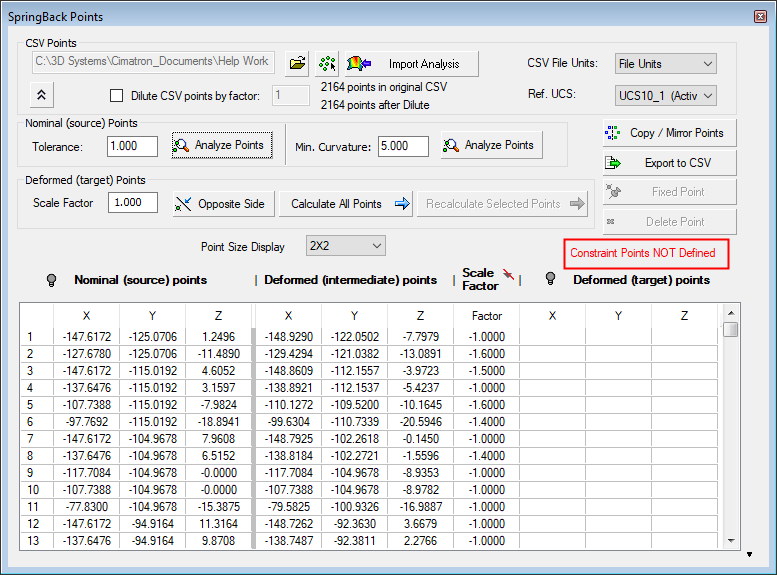
Display the Springback Points dialog containing the coordinates of the source and target points defined from the previous steps of this function. These previously defined target points are initially shown in this dialog as "intermediate"; by setting additional options in this dialog, you can define these target points as final.
Initially, the Springback Points dialog is displayed empty, as shown hereas shown here.
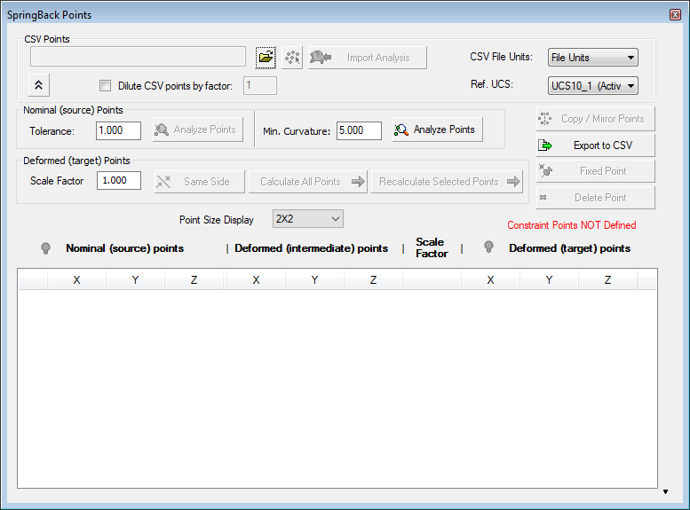
In the CSV Points area of the dialog, either browse to and load the CSV file containing the coordinates of the previously defined source and target points, import a predefined springback analysis, or create a vector data CSV file. This also activates some of the buttons in the dialog, as shown here:
See Springback Points Dialog for an explanation of this dialog.
The Springback Points dialog displays the position of the final target points when they are set (using the parameters in this dialog) and calculated,and the dialog is displayed as shown below. The Deformed (target) points XYZ columns are filled and the dialog displays Constraint Points Defined in green:
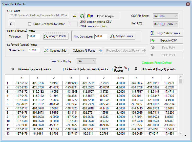
For a description of the field and parameters in the Springback Points dialog, see Springback Points Dialog.
Note: Some FEMFEM programs provide two STL files containing the source and target points respectively. Cimatron enables you to convert these two STL files into a single CSV file so that you can use the By Table option. For additional information, see STL to CSV Converter.
- Click OKOK
 or ApplyApply
 in the Feature Guide to complete the function.
When completed, the Springback Deform or Advanced Warping feature (depending on which function you Variable "iinvoke" is not definededVariable "iinvoke" is not defineded) will appear in the Feature Tree