Cutting Objects dialog: Matrix/Die Plates pane
The Cutting Objects dialog appears in Required Step 3 of the Trimming Punch function. This topic describes the Matrix/Die Plates pane of the Cutting Objects dialog.
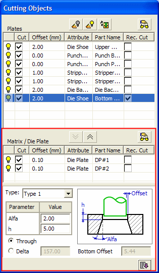
The Matrix/Die Plates pane (marked in red) in the Cutting Objects dialog is shown below (see below for the parameter descriptions of this pane):
|
|
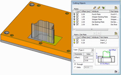
The Cutting Objects dialog includes the following options: The Matrix/Die Plates pane (at the bottom of the Cutting Objects dialog) contains the plates that are tapered cut (cut at an angle). The top part of this pane contains the rows moved from the Plates pane and hence the same parameters are displayed. See the Plates pane for these parameter descriptions. Multiple components can be added to the Matrix/Die Plate pane, which means that in the case of split matrices (where the matrices are placed side by side), all the components in the pane can be tapered cut. In the example below, the matrix is made up of two separate components.
|
Parameters
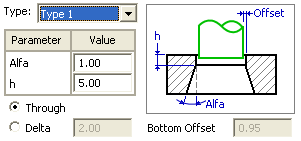
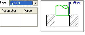
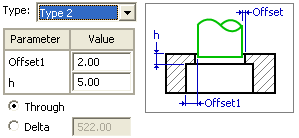
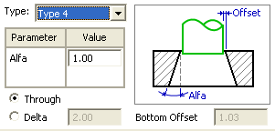
Type: Select the required cutting type as shown in the pictures below:
|
Type 1
|
Type 3
|
|
Type 2
|
Type 4
|
The following parameters are displayed when selecting the Type:
|
Parameter |
Contains the cut parameters,
|
||||
|
Through |
When this option is selected the cut is performed through the plate |
||||
|
Delta |
When this option is selected, the cut will stop at the delta distance measured from the bottom of the plate. |
||||
|
Bottom Offset |
Appears only in Type 1 and Type 4. This option is automatically calculated and shows the offset value relative to the original picked contour on the bottom plate of the die. This offset value is for reference use only. It is recommended to change the offset value of the Lower Die Shoe to be either equal to or larger than the Bottom Offset value. |
||||
|
|
Click the Expand/Collapse toggle button to display the Rectangular Cut Parameters area to define values for each pocket in every plate. |
Notes:
-
Click the
 Preview button at the top of this pane to view the die file plates included in the cut at any time.
 -
Click the
 button to move a selected row from the Plates pane to the Matrix/Die Plate pane. Each time this button is pressed, another selected row is added to the Matrix/Die Plate pane.
 -
Click the
 button to move up a plate from the Matrix/Die Plate pane (where the components are tapered cut) to the Plates pane, (where the components are not tapered cut). If more than one component is available in the Matrix/Die Plate pane, this button is only available when a specific component is selected in the pane.
Multiple Punch Operations
If the Cut option is selected in the 1st required step, you can pick multiple faces and cut all of them at once. In this case, the Part Name column in the Cutting Objects dialog is empty. The parts are cut according to their attributes with no detailed listings.
One feature is created in the component tree, even if it gets cut many times.
- If the Rectangular Punch checkbox is marked and the Bounding Box Offset option (Rectangular Pocket Parameters area) is selected, and different size faces are selected, each punch is created according to a suitable bounding box and offset definitions.
- If the Rectangular Punch checkbox is marked and the Specify Dimensions option (Rectangular Pocket Parameters area) is selected, a rectangular cavity with the specified dimensions is created everywhere, irrespective of the specific bounding box for each face.
