Unbend  : Options and Results
Access: Open this function from one of the following locations:
-
Select Die Design > Forming Shapes > Unbend from the menu bar.
-
Select Unbend from the following Die Design Guide: Die Process Design Guide (Forming).
Unbend and flatten specific areas of the die part along cylindrical and planar faces. The length of the original faces remain the same without any changes after the unbending result is achieved.
Required Step 1 
-
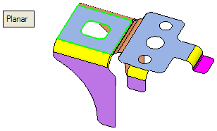
Planar
This option enables you to perform the unbending operation on planar faces.
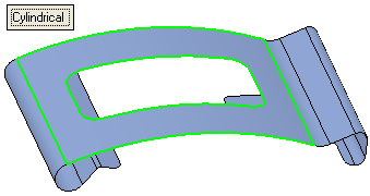
Cylindrical
This option enables you to perform the unbending operation on cylindrical faces, providing the selected faces have linear boundaries.
- ExitExit the step.
Required Step 2 
-
Pick the required cylindrical face (as shown below in the next step, containing the blue arrow). The system automatically identifies (and selects) all the faces containing the same radius and axes. (If required, you can unselect these faces manually.)
Note: If required, you can select additional faces to include in the operation or accept the default faces that were selected automatically. In this case no additional faces were chosen.
- ExitExit the step.
Required Step 3 
-
Pick additional faces to be unbent or unpick some of the system selected faces, as required. Flip the material side (using the blue arrow) if required. The following parameters are displayed:
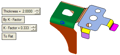
Set the parameters as required:Thickness
Enter the required thickness of the sheet metal in the relevant field. The default value is set to 2 mm.
For an explanation of this parameter, see the Bend function parameters.
By K - Factor / By Elongation
This is a toggle option: By K - Factor / By Elongation:
By K - Factor
Use the K-Factor for the Unbend operation. The following parameter is displayed:
K - Factor
Define the required K factor. The default value is set to 0.333.
For an explanation of this parameter, see the Bend function parameters.
By Elongation
Use the elongation method for the Unbend operation.
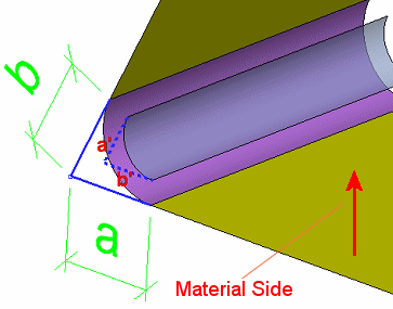
Example:Example:In the By K - Factor option, the length (l) of the flat (purple) face is dependent on the K - Factor, Thickness and Material side. For K - Factor = 0 (irrespective of the thickness or side), the length (l) is the arc length of the cylindrical face.
In the By Elongation option, for Elongation = 0, the length (l) on the flat is equal to a + b.
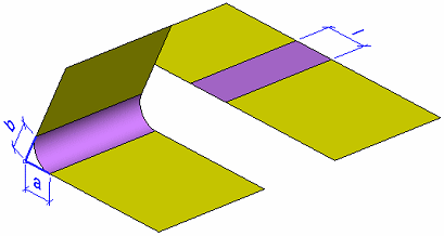
In general, l = a + b + e; where e is the defined elongation and can be either positive or negative. However, e cannot be smaller than (a + b) and there is a limit to its maximum value depending on the material side and thickness.
For example, if the Thickness ≠ 0, and the material side is upwards, and the option On Inner Skin is set (see below), the resulting length is l = a' + b' + e as shown below.
In the same example, if the option On Outer Skin is set, the resulting length is a + b + e.
The following parameters are displayed:
Ref. K - Factor
The Reference K - Factor is for display only. This parameter is calculated by the system and displayed.
The value of this parameter is dependent upon the Thickness value, the material side and the Elongation value. If the Ref. K - Factor value < 0 or > 1, it is displayed in red.
Elongation
Define the elongation value. See the example in the By Elongation description above.
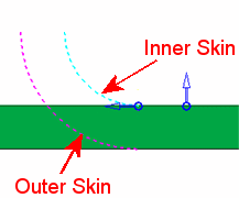
On Outer Skin / On Inner Skin
This is a toggle option to define on which skin to base the By Elongation parameters on.
To Flat / By Angle
This is a toggle option: To Flat / By Angle:
To Flat
Perform a flat unbend operation.
Example - PlanarExample - PlanarThe cylindrical face(s) are automatically selected. Set the parameters and click OKOK .
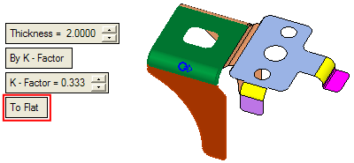
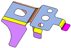
The system flattens the selected faces:
Example - CylindricalExample - Cylindrical
The cylindrical face(s) is automatically selected. Set the parameters and click OKOK .

The result is as follows; the system flattens the selected faces:
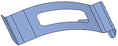
By Angle
Perform a unbend operation by the required angle. The following parameters are displayed:
Angle
Set a specific angle value for the Unbend operation. Possible angle values may be in the range of > 0.001° and < 180°, where 0° is the reference (fixed) face you picked in the 1st required step.
Fix Radius - Fix Center
This is a dropdown list which enables you to define how the Angle value is applied. See below.
Example - PlanarExample - Planar
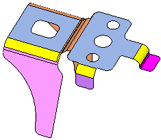
The cylindrical face(s) is automatically selected. Set the parameters and click OKOK .
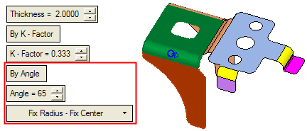
The result is as follows; the system unbends the selected faces by the required angle:
Example - CylindricalExample - Cylindrical
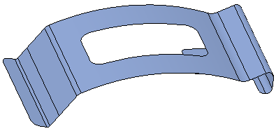
The cylindrical face(s) is automatically selected. Set the parameters and click OKOK .

The result is as follows; the system unbends the selected faces by the required angle:
Fix Radius - Fix Center
This is a dropdown list which is displayed when the By Angle option is selected above. This dropdown list enables you to define how the Angle value is applied. The following options are available:
Fix Radius - Fix Center
The radius is maintained and the cylindrical face is extended and straightened to achieve a fixed length of the neutral plane, as shown in the examples below.
Example:Example:30 Degree Angle:
100 Degree Angle:
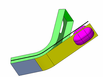
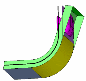
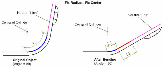
L represents the original length of the cylinder, and when the center of the cylinder does not move (Fix Center) then it is extended (red line) at the end of the cylinder (the blue circle arc), on the neutral line (plane) L = L1 + L2.
If angle is close to 0, L1 will be almost 0 and L2 will be same as L (this is basically the To Flat result).
Fix Radius - Move Center
The radius is kept and the cylindrical face gets a straight extension (the red line below) before the cylinder (the blue circle arc) to achieve the fixed length of the neutral plane.
Example:Example: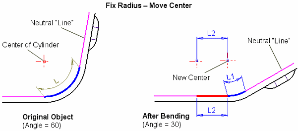
Different Radius
The radius is changed (relative to defined angle) to achieve the same length of the neutral plane.
Example:Example: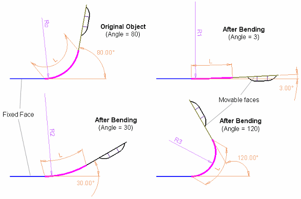
Note: The K Factor multiplied by Thickness (with the side, flip arrow) defines the Offset value.
- Click OKOK or ApplyApply in the Feature Guide to complete the function. The object is unbent as per the defined parameters.
When completed, the new Unbend feature will appear in the Feature Tree:


