Unfold  : Options and Results
Access: Open this function from one of the following locations:
-
Select Die Design > Blanking Tools > Unfold from the menu bar.
-
Select Unfold from the following Die Design Guide: Die Process Design Guide (Forming).
Create flat faces from a simple given 3D model (containing planar & cylindrical faces).
This function provides a geometrical unfolding solution for simple models (planar, cylindrical and conical faces) without using a finite element solution.
Besides the interaction examples, see the additional examples below.
Required Step 1 
- ExitExit the step.
Required Step 2 
- Deselect the faces that will not be unfolded.
- ExitExit the step.
Required Step 3 
-
Flip the material side (using the blue arrow) if required.
-
Set the displayed parameters.
The following parameters are displayed:
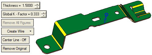
-
Define the required parameters
Thickness
Enter the required thickness of the sheet metal in the relevant field. The default value is set to 1.5.
For an explanation of this parameter, see the Bend function parameters.
Global K Factor
Define the required K factor. The default value is set to 0.333.
For an explanation of this parameter, see the Bend function parameters.
Remove All Figures
Hide all figures from the display.
Create Wire
This is a dropdown list which enables you to define which entities are created as a result of the operation:
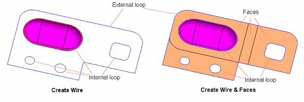
Create Wire
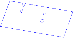
In this case, a wire body is created. This is a peripheral composite (Blank) around the unfold result and a single composite for each internal loop and all faces that are undergoing transformation.
Example:Example: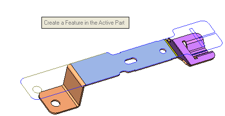
Create Faces
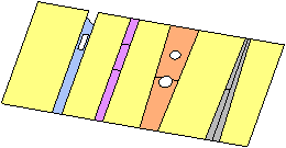
The result will include only the faces.
Example:Example: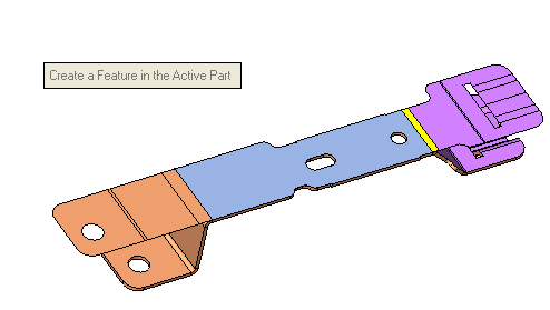
Create Wire and Faces
The result will include wires and faces.
Example:Example: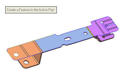
Center Line - Off / Center Line - On
This is a toggle option: Center Line - Off / Center Line - On and enables you to place center lines that mark the original axes of cylindrical faces on the unfolded result.
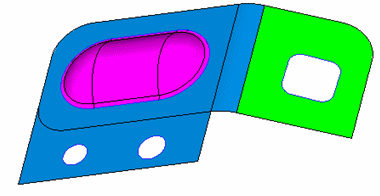
For example, when unfolding the following:
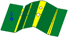
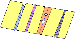
Center Line - Off
Unfold the faces without displaying center lines. This is the default option.
Create Wire option
Create Faces option
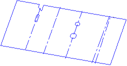
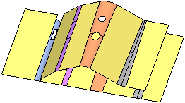
Center Line - On
Unfold the faces and display the center lines in the middle of the relevant cylinder/cone section of the unfolded result.
Create Wire option
Create Faces option
Remove Original / Keep Original
This is a toggle option: Remove Original / Keep Original: and enables you to either remove or keep the original model from the unfolded result.
For example, when unfolding the model used in the above example:
Remove Original
Unfold the faces and remove the original model.

Keep Original
Unfold the faces and keep the original model.
In this case, the default options are selected. No faces were unselected. In addition, you can move the mouse over the selected face for which you want to display the required information, as shown below.
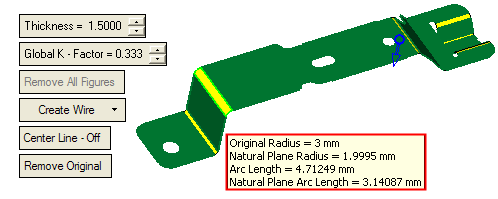
Note: The K Factor multiplied by Thickness (with the side, flip arrow) defines the Offset value.
Optional Step 1  : Pick Additional Faces
-
If required you can select additional faces to include in the operation or accept the default faces that were selected automatically. In this case no additional faces were chosen.
-
Click OKOK or ApplyApply in the Feature Guide to complete the function. The result of the operation depends on which of the following options you selected in the 3rd required step.
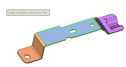
When completed, the Unfold feature will appear in the Feature Tree:

Additional Examples
This option creates an unfolded (flat patter) face from a given 3D model containing planar and cylindrical faces. The reference (fixed) plane must be a planar face. You will be able to pick additional faces (dimples), marked in purple in the picture below. The faces will not be unfolded but will be transformed according to the islands they belong to. See the example below.
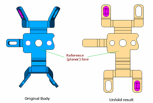
Note: Internal dimples are not selected automatically. Select the dimples in the optional stage to transform them (and not to flatten them).
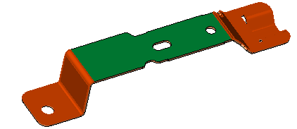
This additional example shows the green face as the Fixed face (selected in step 1), the blue faces are those picked (auto selected) in step 2, and the purple faces are the dimples (optional step 1). The results is shown below:
