|
|
Load Work
The main assembly file is loaded. The file contains the mold assembly.
Four structures are created, one each for fixed side, moveable side, parting, and ejection sub-assemblies.
The parting assembly will later include the work parts and parting face parts. This helps organize the split work.
The layout part holds a coordinate system for every cavity location. In this instance, there are two cavity locations. The outer boxouter box represents an optional mold base size.
This box is a simple sketch that represents a preliminary mold base size. It can be edited to any size to help with the layout until a mold base is built.
We'll now load the work parts into the parting assembly that is currently activated.
-
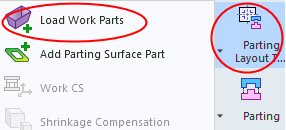
Click Parting Layout Tool > Load Work PartsParting Layout Tool > Load Work Parts.
-
Click Import File and load the Modelxl.igs file that is located in the following folder:
-
Approve the import operation.
-
Mark the Add New Parting Surface Part checkbox to add a new parting surface part along with a work part. Click OK.
-
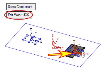
Place the work files on a layout UCS as shown in the following image. This operation also creates a coordinate system in the work file, which is a work UCSwork UCS feature.
To create the work UCS on a specific point (UCS), you need to select it through the reference UCS icon in the Work UCS dialog. (You can create the reference UCS in the model).
-
Click Edit Work UCS.
-
Click Yes to confirm the load operation.load operation.
The system displays the bounding box of the geometry and the centering of the part.
-
Select the lower middle point as the new work UCS.
You can edit any of these values or the layout part center at a later stage. This ensures that there are several ways to control the position of the molded part(s).
-
Click OK twice.