|
|
Slide Units / New Slider  : Options and Results


Access: Open this function from one of the following locations:
-
Select Mold Design > Add Mold Component > Slide Units or New Slider from the menu bar.
-
Select Add Mold Component > Slide Units from the Mold Design Guide Toolbar.
A slider is composed of several parts. These are kept in the catalog as an assembly and can be extracted as required. There is an interaction between the part sizes that you can select to make different groups of pins and also to remove components. At the end of this interaction, a sub-assembly representing the slider is created.
The general interaction is similar to that for adding all mold components from the catalog. However, for each category of mold component to be added (Injection Devices, Plates, etc.), the Component Selection dialog which appears at required step 1, is displayed with the appropriate Category component type automatically selected and the Sub-Category component types displayed. For example, if Plates are selected to be added, the Plate category is automatically selected when the Component Selection dialog is displayed and all the Plate sub-categories are available for selection.
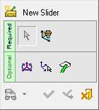
When using the New Slider function to add a slider from the catalog, the Optional Step 3 button is displayed as ![]() (exampleexample) and enables you to position the Angle Pin. See the Optional Step 3 explanation for this function below.
(exampleexample) and enables you to position the Angle Pin. See the Optional Step 3 explanation for this function below.
Required Step 1 
-
Select a slide unit from the catalog.
The Component Selection dialog is displayed with the appropriate Category component type automatically selected and the Sub-Category component types displayed for selection.
See the Add Mold Parts function for a description of this dialog and how to select the size of a component from the catalog.
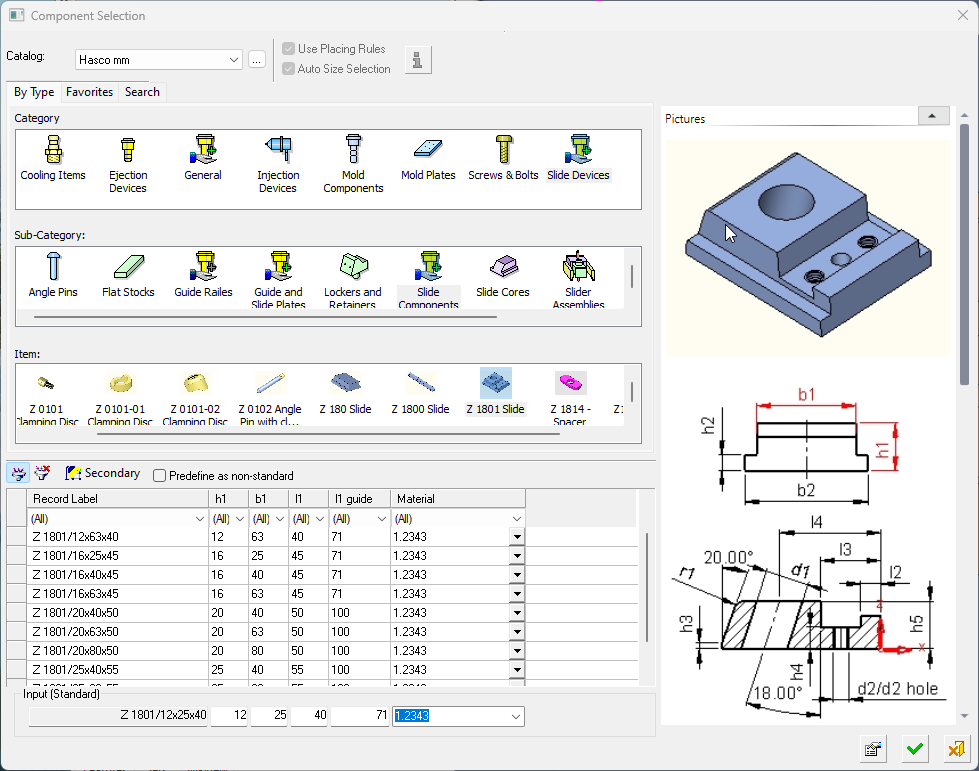 The appropriate Category component type is automatically selected and the Sub-Category component types are displayed for selection.
The Item row of the dialog displays a small image of the actual components, which enables easy recognition of the items. Pick a component item from this row, select the required size record from the catalog table and then position the component on the assembly.
If required, perform the optional steps of this function. - After the Component Selection dialog is displayed, the remaining interaction is identical to that for adding mold parts. However, when using the New Slider function, the Optional Step 3 button is displayed as
 (exampleexample).
Optional Step 3
-
Pick the surface to position the Angle Pin.
Note: This option is only displayed when using the New Slider function.
When adding a slider, the location (or the "height") of the pin head has to be determined. This can be done by selecting a reference plane.
This allows you to pick a plane for placing the slider guide pin (typically this would be the upper face of the top cavity plate).
To support this option, the top face of slide core must have a proper name attached to it (Catalog > Attach Properties to Entity). In addition, you must have a parallel plane with an offset defined as a free parameter. When constructing the slider, the pin is placed upon this plane.
-
Click OKOK
 or ApplyApply
 in the Feature Guide to complete the function.
|