|
|
Cooling Distance Map  : Options and Results

Access: Open this function from the following location:
-
Select Mold Design > Cooling > Cooling Distance Map from the menu bar.
Analyze and create a color map of distances between cooling channels and cooled part faces.
|
|
|
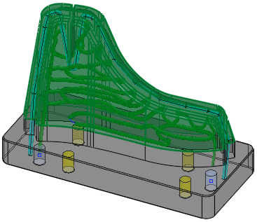
Part on which the function is to be performed |
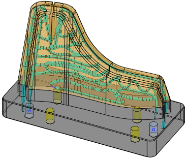
Required Step 1 
Pick/unpick the cooling channels to be analyzed. By default, the system selects all visible cooling lines from the entire assembly, including conformal cooling (faces are recognized as cooling lines if they were created with a cooling function, or the Analyze Conformal Cooling Circuit was used to recognized them). You may add or subtract faces from this selection.
|
|
|
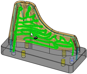
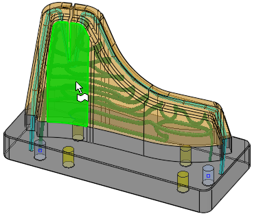
Required Step 2
Pick the faces (usually active faces - faces that touch the plastic) whose distance from the cooling channels will be analyzed in the next step.
|
|
|
|
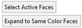
Select Active Faces |
Pick the active faces (faces that touch the plastic). |
|
Expand to Same Color Faces / Do not Expand |
This is a toggle option that enables the selection of faces to be expanded to those of the same color as the first selected face. |
|
Expand to Same Color Faces |
In this mode, when a single face is selected, the selection is expanded to adjacent faces of the same color (as the picked face).
|
|
Do Not Expand |
In this mode, when a single face is selected, the selection is not expanded to the adjacent faces.
|
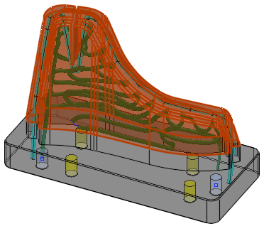
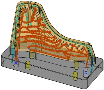
Required Step 3 
Run the analysis to produce a color map of distances between the active faces and the closest cooling line, to assess cooling efficiency. Tweak the color map by changing color ranges and, if required, export the results to a 3D PDF report.
|
|
|
|
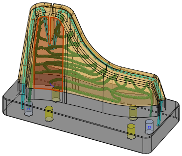
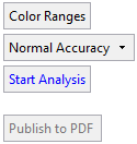
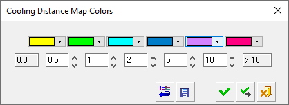
Color Ranges |
Displays a dialog showing color-coded range groups. The colors and the range groups they represent can be customized. Tweak the color map by changing color ranges.
|
||||||||||
|
Normal Accuracy |
This is a dropdown list to define the accuracy level of the analysis.
The available options are Low Accuracy,
Normal Accuracy and High
Accuracy. |
||||||||||
|
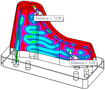
Start Analysis |
Perform the analysis based on the current parameter settings. A progress bar is displayed during the analysis. The result is a distance color map on the selected faces only (not on the cooling channels) of the minimum distance between each point on the faces and the cooling channels. Hover the cursor over the analysis to display a tooltip showing the relevant distance. All faces that do not participate in the analysis are displayed as 100% transparent.
|
||||||||||
|
Publish to PDF |
Publish to PDF to create 3D PDF files that include parts and assemblies from Cimatron. When the Publish to PDF button is selected, a dialog is displayed giving you additional controls before the selected entities are exported to PDF. The Publish to PDF button is
available after an analysis is run (Start
Analysis) and enables you to print the results of the analysis.
|
|