|
|
Symmetry 
Access: Invoke the Sketcher, define the sketch plane and then invoke this function from the following location:
-
Click the Symmetry button
 in the Sketcher
toolbar.
Create or select a symmetry line and enter into symmetry mode.
Create symmetrical copies of entities around one or two symmetry lines. This enables you to mirror geometry around the symmetry line axes.
This tool is useful for any sketching requiring one or two axes mirroring, but it is especially useful when positioning mold components which require positioning in four symmetric locations.
All entities are mutually constrained. The Symmetry tool is used together with a selected drawing tool.
The following options are described here:
|
Demo: Press the button below to view a short movie demonstrating the function: |
|
|
General Interaction
Create symmetrical entities
-
Select a geometry creation tool.
-
Select the Symmetry tool
 .
.The cursor appears in the graphical display area as a crosshair-and-symmetry symbol
 .
. -
Select the required symmetry options (see below) or select an existing symmetry line.
-
The Symmetry tool is now active. The cursor symbol now reflects the drawing tool that was selected in step 1. In the example below, the Circle tool was selected. You can now create symmetrical circles.
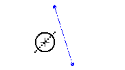
-
Create entities on one side of the symmetry line, and click.
A mirror image is immediately reflected on the other side of the symmetry line.
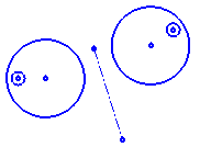
-
Click the Symmetry tool again (to de-select it), or click Select
 , to end the process (Clicking <exit><exit> does not end the symmetry process).
If you move the symmetry line using the Select tool, all the entities that you created while the symmetry process was active (while the Symmetry tool was selected) will be constrained around the symmetry line. In the example below, the symmetry line is moved to the left, causing the images around it to converge.


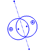
Notes:
-
Symmetry lines also appear when mirroring entities. These symmetry lines can be used after the mirroring operation.
-
When using symmetry lines during regular dimensioning operations, it is important to note that the position on the symmetry line that you pick, could influence the resulting dimension.
1 Axis
-
Select the 1 Axis option.
-
Draw the required symmetry line (or select an existing symmetry line).
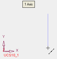
-
Select the required geometry creation tool. In the example below, the Circle tool was selected. You can now create symmetrical circles.
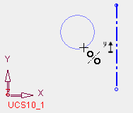
The mirror image is immediately reflected on other side of the symmetry line.
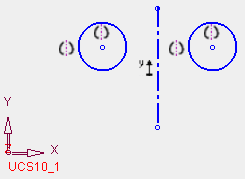
2 Axes - By Point
-
Select the 2 Axes - By Point option.
-
Select a point.
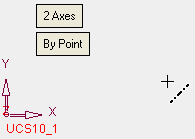
Two symmetry lines are automatically created at the selected point, using the positive sides of the X and Y axes of the sketch. The symmetry lines get horizontal, vertical and coincident constraints.
-
Select the required geometry creation tool. In the example below, the Circle tool was selected. You can now create symmetrical circles.
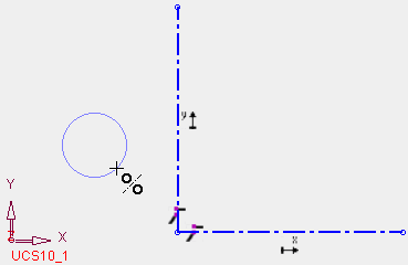
The mirror image is immediately reflected on the other side of each symmetry line.
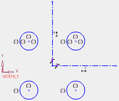
2 Axes - By 2 Lines
-
Select the 2 Axes - By 2 Lines option.
-
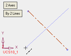
Draw the 2 symmetry lines (or select existing symmetry lines).
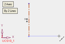
-
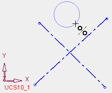
Select the required geometry creation tool. In the example below, the Circle tool was selected. You can now create symmetrical circles.
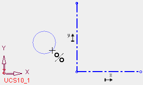
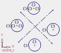
The mirror image is immediately reflected on the other side of each symmetry line.
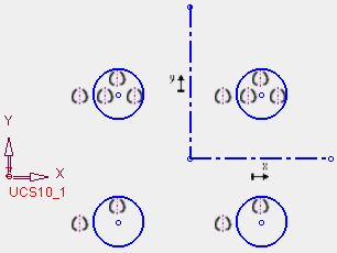
The symmetry lines are created in continuous mode. To create 2 separate lines, exit after creating the first line and then create the second symmetry line. This is shown in the examples below:
The second symmetry line is created.
The geometry is created.
The entities are created in the other quadrants.
Notes:
-
Changing a sketch entity (in any quadrant) will update all entities in all quadrants.
-
Deleting an entity will not delete all entities in other quadrants.
-
The two symmetry lines cannot be parallel to each other. If this occurs, an appropriate warning message is displayed and the second line is deleted (if it was created) or unselected (if it was selected).
Special Cases of Symmetry
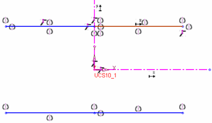
There are a number of special cases when using the Symmetry tool where the usual symmetry 'rules' do not apply.
-
The sketch line ends on the symmetry line:
-
The sketch line passes the symmetry line:
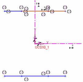
-
The sketch line passes through the UCS origin:
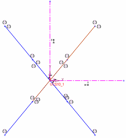
-
A circle or point on the UCS origin is not mirrored 4 times:
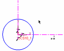
-
One line on the symmetry axis. In the example below, it is not mirrored on the Y axis but only on the X axis:
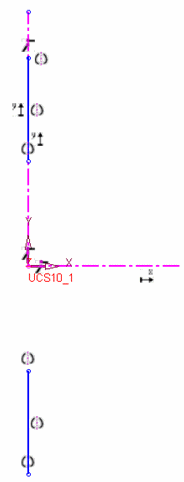
|


