Curvature Map  : Options and Results

Access: Open this function from the following location:
-
Select Analysis > Main Tools > Curvature Map from the menu bar.
Map the different curvature radii of faces and then color the faces giving each range of radii a different color.
Note: The Curvature Map works on B-rep faces and Mesh objects.
For Mesh objects:
- Use the Object Filter from the Quick Geometry Filter to select a Mesh object.
- Due to the faceted nature of Mesh objects, approximate curvature results are obtained.
Required Step 1 
Pick the faces or Mesh objects to undergo curvature analysis and then <exit><exit>.
|
In this example, all the faces are picked. |
|
|
|
|
Required Step 2 
The initial curvature map (the curvature analysis result) is displayed using the default curvature system settings. These settings can be changed using the analysis parameters that are displayed in this step.
The following parameters are displayed:
|
|
|
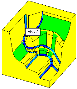
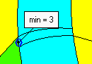
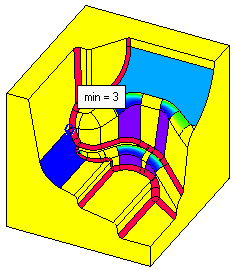
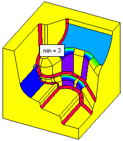
The minimum curvature point is displayed together with its curvature value.
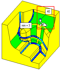
Move the cursor along the faces of the model and note that bubble values appear and change with each face. These values display the local curvature at each point.
|
This face has a curvature value of 40. |
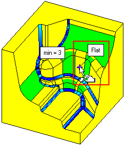
In this case there in no curvature as the face is flat. |
|
|
|
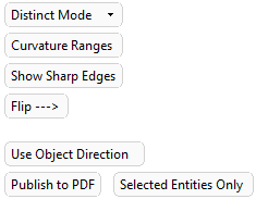
Analysis Parameters
|
Distinct Mode |
The following display modes are available: The system will show 6 distinct colors. Each color represents a range between two radii. Distinct Mode is more suitable for the needs of NC users.
The system shows a variety of colors (up to 213) for different radii. The ranges set milestones of color-radius couples. Each color represents a specific value and the colors change smoothly along the range. Continuous Mode is considered more appropriate for designers.
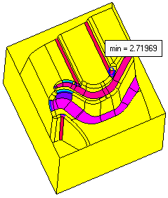
If the triangulation quality is not good, such as in the example below, adjust the Display Quality to the highest value. The curvature map accuracy is heavily dependent on the display quality.
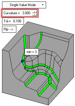
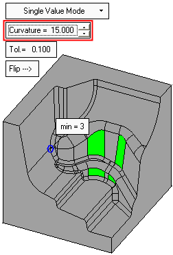
State a specific value and only areas with that exact curvature (within the given tolerance) will be colored. All other faces will be colored gray. In NC, this mode is useful for checking which rounded corners can be finished with a certain tool.
Note: The tolerance here determines the range of radii that will be colored. |
||||||||||
|
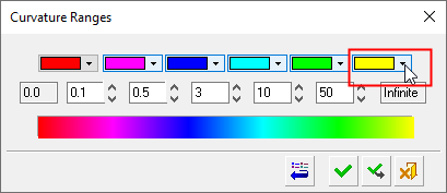
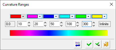
Curvature Ranges |
Displays the Curvature Ranges dialog.
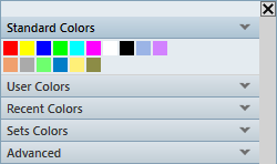
The Curvature Ranges dialog is used to define: The colors that represent specific radii of curvature. The radii that limit the curvature ranges. The color for each curvature range can be changed by selecting the appropriate color button to display a color palette. Pick the required color to represent the curvature range. Default colors and radii values can be set in the Preferences under Modeling/Curvature Map Ranges.
The radii that limit the curvature ranges can be changed either by using the spin boxes or by entering the required value.
In Distinct Mode all the radii in the range between two defined radii will get the color specified between their cells. For example in this case:
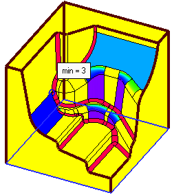
In Continuous Mode the radius in each cell will get a specific color (the one under it). For example in this case:
Depending on the radii values, the changes could have a dramatic visual effect on the curvature map. For example, using the values entered above, the following results occur:
|
||||||||||
|
Hide Sharp Edges |
Hide or Show all the sharp edges. Sharp (or non-smooth) edges are edges which have a two adjacent faces with different normal directions. All edges of non-stitched faces will be marked as sharp edges.
|
||||||||||
|
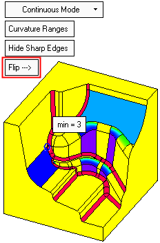
Flip |
Flip the curvature ranges and regenerate the curvature map.
|
||||||||||
|
Use Object Direction |
This is a toggle option Use Object Direction / Use Display Direction that enables you to choose how the curvature map is calculated.
|
||||||||||
|
Publish to PDF |
Publish to PDF to create 3D PDF files that include parts and assemblies from Cimatron. When the Publish to PDF button is selected, a dialog is displayed giving you additional controls before the selected entities are exported to PDF. The Publish to PDF option is only active when the option Use Object Direction is selected; otherwise it is grayed out. Adjacent to this parameter is the toggle option Selected Entities Only / Entire Part which enables you to export only the selected entities or the entire part to PDF. This toggle option is active only if the selected faces are from the same part; if the selected faces are from more than one part, the toggle option is grayed out and set to Selected Entities Only. |


Note: In order to obtain accurate results, you must always look at the part from the same direction that the NC tool would "look" at it. For example, if the part is rotated and viewed from below (if the bottom face is hidden), the colors change dramatically. The reason for this is that the system recognizes the visible side of a face as its "outside".
|
Viewed from above. |
Viewed from below. |
|
|
|
When finished, press Cancel ![]() in the Feature Guide to complete the function.
in the Feature Guide to complete the function.