Cut/Divide Mesh  : Options and Results


Access: Open this function from one of the following locations:
-
Select Mesh > General Tools > Cut / Divide from the menu bar.
-
Select Cut / Divide from the Mesh Guide Toolbar.
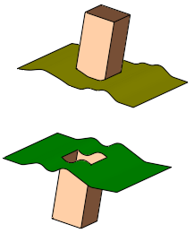
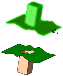
Cut or divide mesh objects.
Required Step 1 
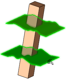
Pick the mesh object(s) to be cut; one or more open or closed objects (including individual faces).
Press <exit><exit> when all objects are selected.
Note: When picking a mesh object, only a single mesh object (closed or open) can be picked.
|
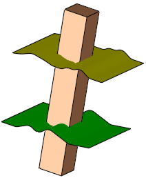
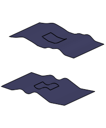
The part before selection: |
The objects to be cut are selected (in this case, open objects): |
|
|
|
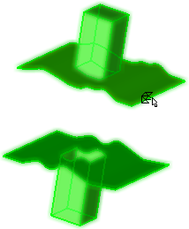
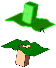
Required Step 2
Pick the cutting geometry; a plane, face(s), open / closed object(s), curve(s), edge(s), axis(axes) or points, and if necessary, indicate the side to be removed.
Notes:
-
If a closed mesh object was selected in Step 1, then following entities can be picked:
-
-
Datum plane
-
Closed mesh object
-
Closed solid object.
-
-
If an open mesh object was selected in Step 1, then following entities can be picked:
-
-
Datum plane
-
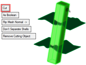
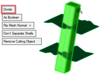
The following parameters are displayed:
|
Cut options: |
Divide options: |
|
|
|
Notes:
-
Use the Selection Filter to select curves, edges, axes or points as the cutting geometry.
-
When selecting a single curve, edge or axis (as the cutting geometry), any geometry which defines a plane can be used as input; a 2D line with an angle, two points and a direction angle, 3 points or 2D curve. See Cut Objects by Curve, Edge, Axis.
-
To reduce the file size when cutting a small object by a large object, instead of using the whole (large) cutting object, the system prompts you to perform the cut operation using only those faces of the cutting object that intersect with the objects to be cut. This prompt is displayed if the following conditions are met:
-
-
If the cutting object (Step 2) is not in the same file as the objects to be cut (Step 1); for example, the cutting object may be in another file of an assembly.
-
If the cutting object has more faces than the objects to be cut.
-
|
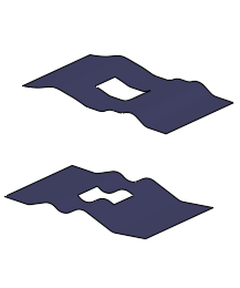
Divide |
This is a toggle option, Cut / Divide, to select the required operation.
|
|||||||||||||||||||||||||
|
As Boolean |
This is a toggle option, As Boolean / As Trim, that enables you to select the method of performing the Cut operation. This option is only displayed if the entity to be cut is an open object.
|
|||||||||||||||||||||||||
|
Flip Mesh Normal |
This parameter is available only for open objects and deals with issues of object direction. |
|||||||||||||||||||||||||
|
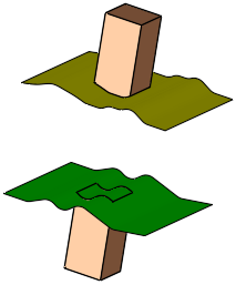
Don't Separate Shells |
This is a toggle option, Don't Separate Shells / Separate Shells, that enables you to decide whether shells remaining after a cut operation are to be regarded as a single shell or as separate shells.
|
|||||||||||||||||||||||||
|
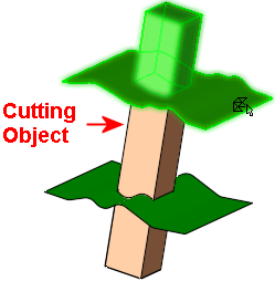
Keep Cutting Object |
This is a toggle option, Keep Cutting Object / Remove Cutting Object, that enables you to decide whether or not the cutting object is removed after a cut operation.
Notes:
|
|||||||||||||||||||||||||
|
Extend |
This is a toggle option, Extend / Don't Extend, that enables the extension of a cutting planar or non-planar face, to cut the object selected in step 1. This option is only displayed if the cutting object is a face or multiple faces. For planar faces:
For non-planar faces only: If the Extend option is selected, an additional toggle option Natural / Tangent is displayed.
Example:Example:
Single curve, edge or axis:
|
|||||||||||||||||||||||||
|
Transfer Attributes |
This is a toggle option, Transfer Attributes / Don't Transfer Attributes, that enables you to decide whether or not to transfer attributes (colors, threads and hole attributes) with the cut operation.
Notes:
|
|||||||||||||||||||||||||
See Facet Selection for a description of the various facet selection options.
Press OK ![]() or Apply
or Apply ![]() in the Feature Guide to complete the function.
in the Feature Guide to complete the function.
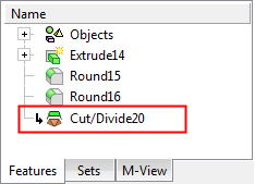
When completed, the Cut/Divide feature appears in the Feature Tree as follows: