|
|
Components  : Options and Results

Access: Open this function from one of the following locations:
Define plates, components, and inserts.
This information can either defined automatically based on the Plates predefined attributes, or manually; the Component Table displays the relevant data. This information is used later when generating quoting data. The predefined data is defined during the Quoting Setup process.
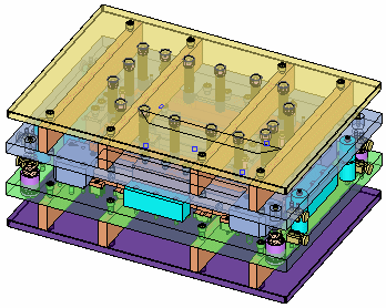
The following assembly is used to describe this function:
Required Step 1 
-
Add predefined components or plates, or create a new component or plate set to be added to the Component Table (displayed in the function). The following parameters, and the Component Table (see below) are displayed:
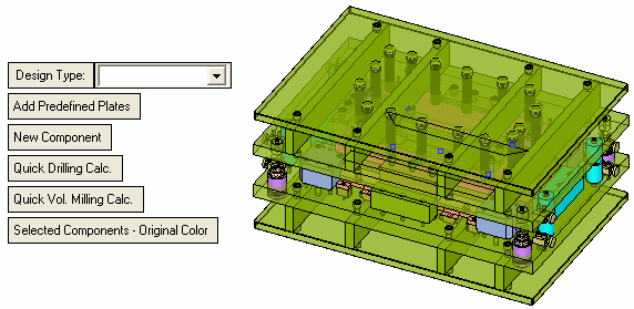
Note that some of the plates are now displayed in a default selected color. This signifies that these plates, together with all the calculated data (Drill Hole Depth, Wire-EDM Length, Volume Milling, Surface Milling), have already been added to the Component Table. However, you can choose whether to display these plates in the selected color, or in their original colors (you can also change the selected plate color in the Component Table).Design Type
Select the design type from the dropdown list. This data appears in the Type column of the Component Table.
This contents of this dropdown list are defined during the Quoting Setup process, for example:
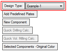
Add Predefined Plates
Add all predefined plate sets to the Component Table (see below).
The plates, together with all the calculated data (Drill Hole Depth, Wire-EDM Length, Volume Milling, Surface Milling) are added to the plate table.
New Component
Pick a new component to be added to the Component Table and <exit><exit> when finished.
The component, together with all the calculated data (Drill Hole Depth, Wire-EDM Length, Volume Milling, Surface Milling) is added to the component table.
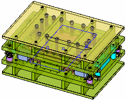
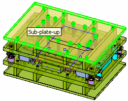
Example:Example:The top component is to be added to the Component Table.
Place the cursor on the component to display a popup showing the component name. Then select the component to add it to the Component Table.
Quick Drilling Calc.
Recalculate all drilling values. This updates the values in the Drill Hole Depth column of the Component Table. A message is displayed requiring user confirmation to complete the operation.
Quick Vol. Milling Calc.
Recalculate all volume milling values. This updates the values in the Volume Milling column of the Component Table. A message is displayed requiring user confirmation to complete the operation.
Selected Components - Original Color
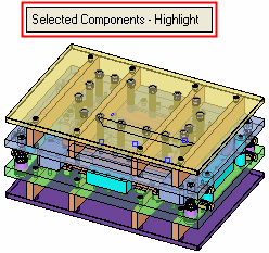
This is a toggle option (Highlight / Original Color) enabling you to choose how selected components (those components already added to the Component Table) are colored in the display area.
Example:Example:Highlight: The plates added to the Component Table are displayed in a default highlight "selected" color.
Press the toggle button to display these components in their original colors.Original Color: The plates added to the Component Table are displayed in their original colors.
Press the toggle button to display these components in the highlight "selected" color.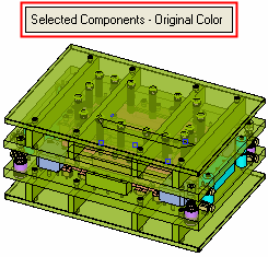
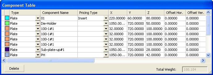
The following Component Table is displayed showing the defined component sets and their parameters:
Notes:
-
Selecting a row (plate) in the Plate Table, highlights the appropriate plate in the display, and vice versa.
-
All columns are editable, except for the read-only summary columns (Drill Hole Depth, Wire-EDM Length, Volume Milling, Surface Milling).
Color
Set the color of the plate by picking the color icon and selecting the color from the displayed color palette.
Type
The selected Design Type.
Component Name
Name of the component. By default = ‘Plate1’, ‘Plate2’, etc.
Pricing Type
Select the pricing type from the dropdown list in the table field. The default values are based on the selected Design Type value.
XYZ
The dimensions of the selected plate. These fields are calculated automatically.
Offset Hor.
Set a horizontal offset for the component.
Offset Ver.
Set a vertical offset for the component.
Material
Select the component material from the dropdown list in the table field. The default value is based on the selected Design Type value.
Hardness
Select the component hardness from the dropdown list.
Weight
The weight of the component.
Qty.
Define the quantity of plates in the plate set.
Complex Factor
Set the complexity factor of the plate. By default = 1. This can be used to calculate machining time from machining information based on the factor.
Drill Hole Depth
Read-only summary fields showing the calculated values of the user-defined parameters.
W-EDM Length
Volume Milling
Surface Milling
Comment
Enter a comment as required.
The following appear at the bottom of the table:
Delete
Delete a selected row in the Component Table. This deletes the selected row (component set), together with all its calculated data. A warning message requiring confirmation of the deletion is displayed.
Total Weight
A read-only summary field showing the calculated total weight of all the components.
-
-
Click OKOK
 or ApplyApply
 in the Feature Guide to complete the function.
|