|
|
Trimming Punches  : Options and Results
Access: Open this function from the following location:
-
Die Design > Die Quote > Trimming Punches from the menu bar.
Define trimming and piercing punches. These punches are cut by Wire-EDM and are, therefore, priced according to the contour that needs to be cut and the required stock material.
The Punch Table displays the relevant data. This information is used later when generating quoting data.
The following assembly is used to describe this function:
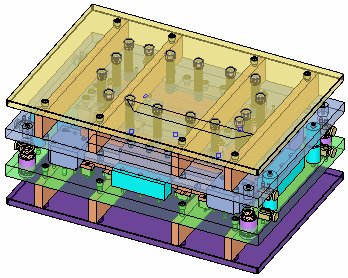
When you openopen this function, the Punch Table (see below) is displayed:
Required Step 1 
- Add predefined punches or create a new punch set. The following parameters are displayed:
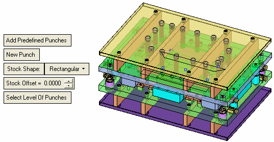
Add Predefined Punches
Add all the predefined punches to the Punch Table (see below). Predefined punches are those who have a "Punch" attribute assigned to them by using the Assign Trimming Punch function.
New Punch
Pick a face and <exit><exit> to create a new punch set. A new row is added to the Punch Table (see below), where the function automatically calculates the punch length and machining boundary of the selected face.
The following parameters are displayed:
Ignore Assigned
Faces already assigned as punch sets cannot be selected; they are ignored.
Select All
All faces can be selected, including those already assigned as punch sets.
Stock Shape
Select the shape of the stock from the dropdown list. The available options are Rectangular, Rounded or Shaped.
Stock Offset
Define the stock offset.
Select Level of Punches
Select the punch level. A datum plane is displayed at the current punch level; select a different face to move the punch level.
Examples:Examples:Datum plane signifying the current punch level.
Select a different face to change the level.The datum plane moves to the new level.
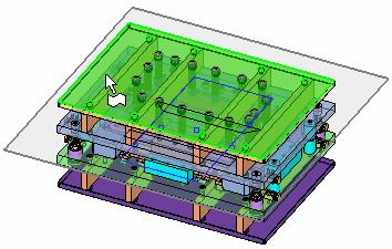
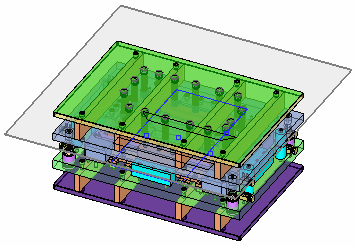
The following Punch Table is displayed showing relevant data for the punch sets:
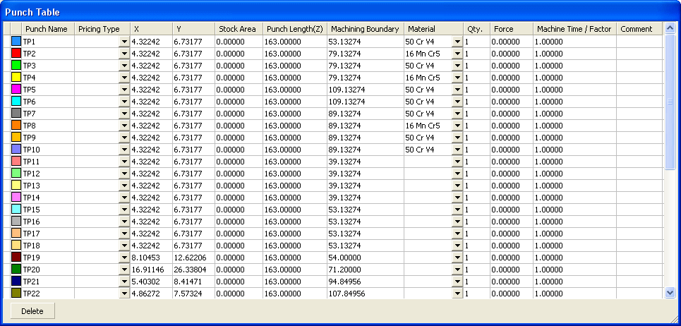
A row of data in the table always takes values from the previous row (if available).
Color
The color of the punch sets are defined automatically. Change the color by picking the color icon and selecting the color from the displayed color palette.
Punch Name
The punch name is defined automatically and consists of an automatic numbering sequence (TP1, TP2, etc.).
Pricing Type
Select the required type from the dropdown list.
XY
The dimensions of the selected face. These fields are calculated automatically.
Stock Area
The stock area is calculated according to the Stock Shape and the Stock Offset values in the screen parameters.
Note: If you select a row (punch set) in the Punch Table and then change the Stock Shape or Stock Offset parameter values, the Stock Area is recalculated and overridden.
Punch Length (Z)
The punch length - the Z height of the selected face.
Machining Boundary
The default calculated machining boundary is dependent on the bounding box (rectangular) of the selected face. It is calculated and registered as X, Y values.
Material
Select the required material from the dropdown list.
Qty.
Define the quantity of punches in the punch set.
Force
Define the force required.
Machine Time / Factor
Set the required machining time factor. The last defined machine time is used for any new operation. By default this is set to 1.
Comment
Enter a comment as required.
The following appears at the bottom of the table:
Delete
Delete a selected row in the Punch Table. This deletes the selected row (punch set), together with all its calculated data.
- Click OKOK or ApplyApply in the Feature Guide to complete the function.
|
