Parting Guide Toolbar

Access: To show the Parting Guide Toolbar, right-click a currently displayed toolbar and select the Parting checkbox from the popup list of available toolbars.
To hide the toolbar, unselect the checkbox.

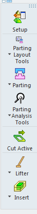
The Parting Guide toolbar, located on the right side of the Cimatron window, lists the Parting Functions in a logical order to guide you through the parting process, from start to finish.

These functions are also available under the Mold Design or Parting menus or the Mold Toolbar.

How to show or hide this guide

Notes:

The Parting Guide toolbar steps are detailed below. See the MoldDesign Functions and Parting Functions for additional information on these functions.

Parting Guide
Toolbar:

Assembly Active

Parting Guide
Toolbar:

Part Active

Function Description

Setup. Summary:Summary:

Open the Setup table and define default parameters for the mold layout. These include data for bounding, delta sizes, shrinkage factor, and more.

Parting Layout Tools. Summary:Summary:

This group of functions is used to add and edit a Layout part. A Layout part is a pattern of coordinate systems used to place the work parts (the next step in the Mold Design Guide Toolbar and Parting Guide Toolbar) within the mold. A layout part can be selected to meet the requirements for either a single or multiple cavity design. Each work part will be placed using a single coordinate system. You can also add a Layout part from the Mold Project Setup Wizard.

The following optionsoptions are displayed.

Add Layout

Create a Layout Part as a skeleton for the multi cavity.

Add Parting Sub-Assembly

Add an existing parting sub-assembly.

Add Parting Surface Part

Create a new parting surface part.

Layout UCS

Create a UCS to be used as a layout UCS and have work parts placed on it.

Load Work Parts

Import or add a work part to the assembly and position the work part onto the UCSs in the Layout Part. With this function, you can create a new work part from a master part file or load an existing work part. 

Mark as Work Part

Mark a part as a work part.

Shrinkage Compensation

Apply Shrinkage Compensation to compensate for part shrinkage during the mold material cooling process, after removal from the mold  and cooling to room temperature.

Update Setup Bounding Data

Update the size of the bounding box around the work part(s) that are shown in the Setup Mold Layout tab.

Work CS

Create the main reference UCS (Work CS) in the work part, defining the position of the work part in the assembly.

Parting. Summary:Summary:

This group of functions is used for performing Parting operations.

The following optionsoptions are displayed.

Edit Split Direction

Edit a previously defined split direction. When you edit a direction, the faces that belong to this direction are automatically selected.

Highlight Split Direction

Highlight the split direction of a face.

New Direction

Invoke the QuickSplit function and create a new opening direction.

Parting Attributes

Assign parting attributes to parting surfaces (faces)parting surfaces (faces). This attaches the parting surfaces to opening directions.

Parting surfaces separate the core and cavity mold halves; they are the contact surfaces of the two halves of the mold. Parting surfaces do not form the molded part.

QuickSplit

Split faces into opening directions based on their ability to be extruded in those directions and existing parting surfaces.

Parting Analysis Tools. Summary:Summary:

This group of functions is used for performing Analysis operations.

The following optionsoptions are displayed.

Delete Analysis Marks

Delete selected analysis marks created by the last used analysis operation. The markings are areas indicated as problematic during the analysis.

Direction Analysis

Analyze selected faces and visualize their draft angle with reference to a defined direction.

Draft Angle Analysis

Analyze faces assigned to opening directions and display their drafting angles with reference to those directions.

Hide/Show Analysis Marks

Hide or show the analysis marks created by the last used analysis operation. The markings are areas indicated as problematic during the analysis.

Parting Analytic Tools

Analyze the quality of the parting (QuickSplit) work and parting surfaces creation.

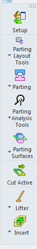
Parting Surfaces. Summary:Summary:

This group of functions is used for Parting Surface operations.

The following optionsoptions are displayed.

Cut Active. Summary:Summary:

Cut a part by active and parting surfaces of an opening direction.

Lifter Tools. Summary:Summary:

This group of functions provide a simple automated way to create lifters and enable you to establish pockets in the core and cavity at a very early stage in design, so that time-consuming wire EDM and milling operations can begin on the first day of design.

The following optionsoptions are displayed.

Add Lifter

Add a lifter part from the catalog.

Cut Lifter

Cut a lifter by active and parting surfaces.

Cutting Object

Create a new object that will be marked and used as a cutting object.

Lifter Pocket

Insert a cavity in the relevant active part(s) to make room for a lifter.

Insert Tools. Summary:Summary:

This group of functions provide a simple automated way to add inserts and enable you to establish pockets in the core and cavity at a very early stage in design, so that time-consuming wire EDM and milling operations can begin on the first day of design.

The following optionsoptions are displayed.

Add Insert

Create the insert geometry and its cutting object including reliefs and cut the plate with it.

Add Insert from Catalog

Add an insert part from the catalog.

Add New Part

Add a part/component to the assembly/sub-assembly.

Add Wedge

Add a wedge to a solid object to lock it in position. A cutting object can also be selected.

Automatic Cut

Cut component(s) automatically by component(s) with Cutting Objects according to their cutting rules.

Cut Inserts

Cut an insert by active and parting surfaces.

Cutting Object

Create a new object that will be marked and used as a cutting object.

Extrude

Extrude a contour to add or remove material.

Insert Pocket

Insert a cavity in the relevant active part(s) to make room for an insert.

Sketcher

The Cimatron Sketcher is the graphic environment used to create sketches - 2D parametric geometry. The 2D geometry can then be used elsewhere in Cimatron's hybrid environment, such as in Part Modeling functions or in NC. The Sketcher is a powerful, yet intuitive, tool enabling you to create and modify entities in relation to each other.

Showing or Hiding the Parting Guide Toolbar

To hide or show the Parting Guide toolbar, click the Access button at the top of this Help topic for instructions.

Some functionality may be dependent on the product package. Contact your Reseller if you require a license.