|
|
Draft Angle Analysis  : Options and Results

Access: Open this function from one of the following locations:
-
Select Parting > Draft Angle Tools > Draft Angle Analysis from the menu bar.
-
Select Parting Analysis Tools > Draft Angle Analysis from the Mold Design Guide Toolbar or Parting Guide Toolbar.
-
Select Draft Angle Analysis from the popup submenu when it is activated on a split directionsplit direction(for example,
 )
in the Parting Tree.
)
in the Parting Tree.
-
The Draft Angle Analysis dialog is also displayed in Direction Analysis.
Analyze faces assigned to opening directions and display their drafting angles with reference to those directions.
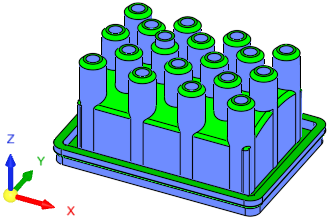
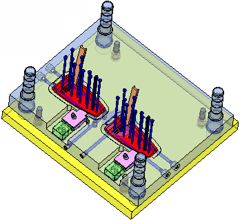
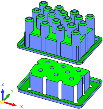
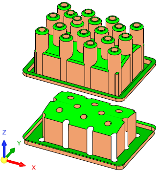
Prior to performing Draft Angle Analysis, the QuickSplit function must be run so that the part objects are divided into Sets. After running QuickSplit, the draft angle of the model is automatically color-coded according to the default color map values, based on zone thresholds (as shown in the picture below). The Draft Angle Analysis tool enables you to graphically analyze the draft angles of each face.
Required Step 1 
Set the opening direction. The following interaction is displayed:
|
Within the Part environment. |
Within the Assembly environment. |
 |
|
|
|
|
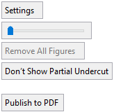
Settings |
Display the Draft Angle Analysis dialogDraft Angle Analysis dialog. See below for additional information. |
||||
|
|
Use the slider to separate the previously split parts.
|
||||
|
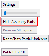
Hide Assembly Parts / Show Assembly Parts |
This is a toggle option displayed within the Assembly environment that toggles between Hide/Show Assembly Parts. When in Hide mode, all the assembly parts are hidden, except for the active parts, to improve clarity.
|
||||
|
Remove All Figures |
Click the Remove All Figures button to remove all the angle value labels from the display. This option is grayed out if there are no angle value labels in the display. |
||||
|
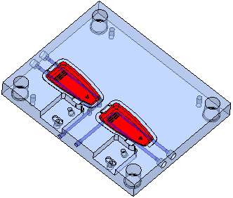
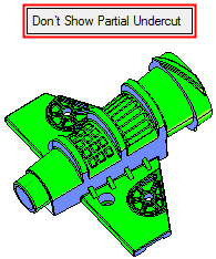
Show Partial Undercut / Don't Show Partial Undercut |
This is a toggle option Show Partial Undercut / Don't Show Partial Undercut to enable you to show partial undercuts for analysis, or not to show them. For all system calculations, there is a correlation between the required accuracy level and the duration of the calculations; setting a higher accuracy level will extend the calculation time.
|
||||
|
Publish to PDF |
Publish to PDF to create 3D PDF files that include parts and assemblies from Cimatron. When the Publish to PDF button is selected, a dialog is displayed giving you additional controls before the selected entities are exported to PDF. |
Draft Angle Analysis Dialog
-
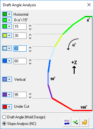
Select Settings in the screen parameters. The Draft Angle Analysis dialog is displayed.
Displaying draft angle analysis
The draft angle of the model is automatically color coded according to the default color map values based on zone thresholds. As shown above, the opening directional arrow is in the +Z direction, clearly showing the faces that are considered vertical and horizontal.
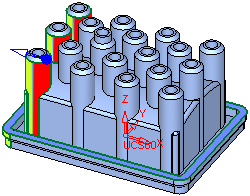
An example of an analysis showing an under cut area can be seen hereseen here. In this case, the opening directional arrow is in the -X direction.
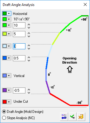
The color map values (based on zone thresholds) can be modified (see Changing the Colors section below) and are divided into the following zones:
-
Horizontal
-
10° < a° < 90° for Draft Angle Analysis
(in the Cimatron MoldDesign application)
0° < a° < 15° for Slope Analysis
(in the Cimatron Numerical Control (NC) application) -
2 user-definable thresholds
-
Vertical
-
1 user-definable threshold
-
Undercut
Cimatron runs the Draft Angle Analysis on the selected faces according to the selected direction. You can change the arrow direction and the analysis will be updated automatically.
The draft angles of points can also be displayed (see Displaying the draft angles of points below).
Notes:
-
Default colors and their values can be defined in Tools > Preferences > Modeling > General.
-
The displayed color changes are only temporary. Once the function is exited, the original colors of the objects are displayed.
-
The default color of objects that are not split is defined in Tools > Preferences > Modeling > Color > Geometry (objects).
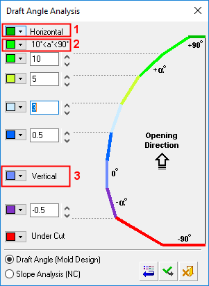
Changing the colors
Select the color to be changed and select the required color from the Color Palette dialog.
The new color is immediately displayed in the color button of the relevant angle segment. When you click ApplyApply
 in the Draft Angle Analysis dialog, the color of all appropriate faces in the model that match the zone thresholds are changed.
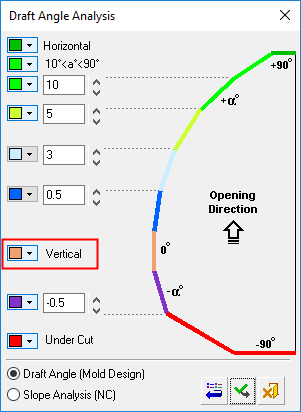
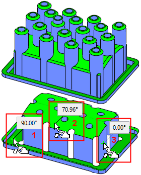
Displaying the draft angles of points
To display the local draft angle at any point on a face, move the cursor over the appropriate face. The cursor changes to
 and the local angle at the point indicated by the cursor is displayed in a label (if required, pick the face to attach the label to it).
The presented angle is between the direction arrow and the tangential line on the cursor point. As shown below, the opening directional arrow is in the +Z direction. Also, note that the Remove All Figures option is available (not grayed out) as angle value labels are attached to faces (select this option to remove these labels from the display).
-
-
Modify the threshold values on the dialog by entering new values manually or by clicking the arrows to increase or decrease the values by increments of 0.5.
-
Either click Restore DefaultsRestore Defaults
 to restore the default colors and values from Preferences, ApplyApply to apply the new draft angle color ranges, or CancelCancel
  to exit the function.
Notes:
-
Each operation that changes any of the objects (split, attach faces, delete, etc.) is followed with an immediate recalculation of the draft angle analysis.
-
If a Parting Surface exists, it is also included in the draft angle analysis.
-
|