|
|
Break View 

Access: Open this function from one of the following locations:
-
Click the
button in the toolbar. -
Select Views > View Creation > Break View from the menu bar.
-
Select Break View on the popup menu in the Drawing Tree (right-click the relevant View
 in the Drawing Tree).
Create a broken (shortened) view of a long part in Drafting. Broken views can be created with adjustable break lines in a variety of styles. Any dimension made in a broken view is still correct to the part model, as it will automatically compensate for the part length that has been broken away.
Broken views can be created on a simple section or any other type of view.
The Break View dialog is displayed:
|
|
Pick the view to be broken, define the direction of the break lines and set the parameters. Default settings for the break line distance, shape, overshoot, pen style, line style and color are defined in the Broken View Preferences. However, the last-used parameter settings are kept for all the parameters in the dialog. |
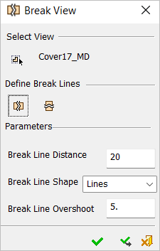
Parameters
Default settings for the break line distance, shape, overshoot, pen style, line style, and color are defined in the Broken View Preferences.
|
Select View |
Pick the view to be broken; the selected view is highlighted. If the function is invoked from the Drawing Tree, the relevant view is already selected and highlighted. |
||||||||
|
Define Break Lines |
Set the direction of the break lines and then define the 2 break lines:
Define the 2 break lines.
|
||||||||
|
Break Line Distance |
Set the distance between the break lines after the clipping.
|
||||||||
|
Break Line Shape |
Set the shape of the break lines used for the clipping, from the dropdown list. The following shapes are available:
The break lines can be dragged in the relevant directions (left and right for vertical break lines or up and down for horizontal break lines). Multiple break lines can be added to a view.
|
||||||||
|
Break Line Overshoot |
Set the distance beyond the geometry to which the break line extends.
|
Press the OK ![]() or Apply
or Apply ![]() buttons to complete the operation. In the Drawing Tree, for each break performed on a view, a sub-node is added to the broken view, for example:
buttons to complete the operation. In the Drawing Tree, for each break performed on a view, a sub-node is added to the broken view, for example:
Notes:
-
When a view becomes broken it loses any alignment that is in the direction of the lines (if a vertical break is added, the vertical alignments are lost, etc.). It will stay at the same position, but will no longer be aligned in that direction.
-
If alignment is defined manually for a broken view (if it is in the direction of the break), then it will be based on the center of bounding box (as with views of different scale or models).
-
If a view is derived from a broken view (including sections), all breaks in the relevant direction are applied to the new view, and the views are aligned. However, the breaks are not associative and if any of them is edited, the associativity is lost.
-
When creating a break on a rotated view, the vertical and horizontal directions are taken from the model, not from the rotated view.
-
A broken view cannot be activated.
Broken Dimensions
Broken dimensions are created automatically when you create a linear distance dimension between two entities that are separated by break lines (only in broken views). For linear dimensions, the broken dimension line is displayed with a jog (angular dimensions have no jog).
The dimension value that appears when using the Numeric-Automatic method, is the actual distance between the entities on the model (before breaking the view), as shown below:
|
Actual distance: |
Broken dimension (with a jog) displaying the actual distance: |
|
|
|
If a break is added to a view, all dimensions that have both ends still visible, but with a clipped area in the middle, turn to broken dimensions.
When removing a break, all relevant dimensions turn to normal dimensions.
Suspending/Unsuspending Broken Views
In some cases (see the examples below) it may be necessary to suspend a broken view in order to perform additional operations on it.
Suspend a broken view
- Right-click on a broken view item in the Drawing Tree to display the broken view popup submenu.
- Select the Suspend option. The following occurs:
-
This will unbreak the view but keep the break definitions.
-
It will add the suspended S mark next to the break icon on the tree as shown below.
|
|
|
Notes:
-
When a broken view is suspended, the Suspend option in the broken view popup submenu is replaced by the Unsuspend option. Using the Unsuspend option will re-break the view using the saved definitions.
-
Activating a view does not suspend or un-break it.
-
Both Suspend and Unsuspend work on all the breaks of that view.
-
When a Suspend or Unsuspend is invoked, an appropriate message is displayed prompting you to approve or cancel the operation.
Examples of operations requiring the broken view to be suspended:
-
When trying to use any tool that requires opening the Sketcher on a broken view that is not suspended, an appropriate message is displayed informing you that a Sketch cannot be created on a broken view, and prompting you to suspend the break. If approved, the break is automatically suspended.
-
When double-clicking a group that is part of a broken view in order to move it, an appropriate message is displayed informing you that a group cannot be moved on a broken view, and prompting you to suspend the break. If approved, the break is automatically suspended.
|