Drawings
Access: To create a drawing, create a new Drawing (Drafting) file.
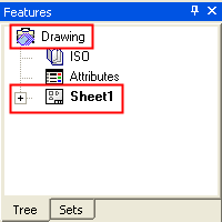
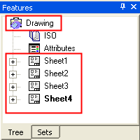
The file used in the Cimatron Drafting environment is called a Drawing. When a drafting file is created, a drawing and one sheet are automatically created. Multiple sheets can be added to the drawing file. This structure is displayed in the Drawing Tree.
|
Drawing with one sheet: |
Drawing with multiple sheets: |
|
|
|
The default drawing name is 'Drawing'. To rename a drawing, right-click on the drawing item in the Drawing Tree, select Rename and enter the new drawing name. You have the option to also set view attributes. If view attributes are not established, the defaults for the drawing will be used. Defaults are defined in the Drafting Preferences.
Drawings
The drawing contains 3 main sections on the screen:
-
The drawing menu bar and toolbar enabling you to choose the required option and create the drawing.
-
The drawing tree enabling you to control the drawing by selecting different options from the drawing tree.
-
The graphic area where the drawing is created and displayed.
The following options allow you to create different geometries and add drafting annotations to the drawing:
-
Add, copy or delete sheets from the drawing.
-
Create a Frame - create a frame in a specified size and add it to the sheet.
-
Define a Drawing Standard - add the desired drawing standard to the sheet.
-
Define the view attributes - (visible or hidden lines, color, pen and style) define the required view attributes for the view.
-
Add a 2D view from the selected model - add a 2D view from to the drawing from an Cimatron part or assembly model.
-
Add 2D geometry using the sketcher - add and create the geometry using the 2D sketcher.
-
Hide/Show curves in the drawing.
-
Add drafting annotations - add various drafting annotations to your drawing. The following annotations can be added:
-
Dimensions: Add various dimensions to the drawing.>
-
Geometric Tolerance: Add a geometric tolerance to the drawing.
-
Geometrical Datum :Create a datum reference for a point on the screen or curve.
-
Datum Target: Add a datum target symbol to the drawing.
-
Surface Roughness: Add a surface roughness symbol to the drawing.
-
Section Line: Add a section line to the drawing.
-
Center: Add a center line to the circle or arc in the drawing.
-
Symmetry Line: Add a symmetry line to the drawing.
-
Arrow: Add an arrow to the drawing.
-
Weld: Add a Weld symbol to the drawing.
-
ID Number: Add an ID number to mark the drawing.
-
Hatch: Add hatch lines to the drawing.
-
Text: Add text symbols to the drawing.
-
BOM: Import a Bill of Materials into the drawing.
-
Insert Picture: Embeds graphic files into a drawing.
-
Contour: Define a Contour.
-
-
Hide & Show geometries and drafting entities in the drawing - hide undesired geometries or drafting annotations from the view using the Hide
 and Show
  icons.
 -
Edit the parameters a group of entities in a single interaction
-
Move or order a group of entities according to selected parameters
-
Align the drafting symbols.
-
Change the line attributes of the drafting annotation - modify the drafting annotation's color and line width.
-
Update the drawing - update the drawing to incorporate changes to the model.
-
Create templates and apply them to drawings or sheets.

