View Attributes 

Access: Open this function from one of the following locations:
-
Select Views > Tools > View Attributes from the menu bar.
-
Select Set View Attributes on the popup menu in the Drawing Tree (right-click the relevant Sheet
 or View
  in the Drawing Tree).
 -
Double-click the Attributes item
in the Drawing Tree. -
Click the View Attributes button
in the View Creation dialog.
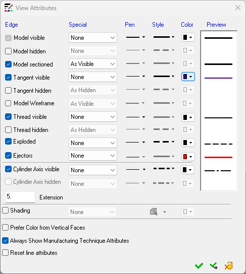
Set the visibility conditions of various entities (line pen, style, and color) in views by defining their view attributes.
These attributes define how the various entities are displayed in views. The defaults for these attributes are defined in the View Attributes Preferences.
View Attributes dialog
The View Attributes dialog is displayed (additional information is displayed in the dialog when a view of an assembly is created (see the Assembly View - View Attributes dialog below).
-
In the View Attributes dialog, set the visibility attributes of the entities by selecting or deselecting the appropriate checkboxes.
|
|
The view attributes of the following entity categories can be defined:
See also: |
-
Click OK to apply the selected attributes.
Attribute types
For most entities, the following attributes can be assigned. The Preview column shows how the resulting entity will be displayed.
-
Special (see Special visibility attributes below)
-
Pen
-
Style
-
Color
For Shading, the following attributes are available:
-
Special
-
Transparency level (Wireframe, Transparent, Shade, or Render Mode)
-
Color
Each of these entities has one or more of the following Special visibility attributes that can be set from the adjacent drop-down list.
Special visibility attributes
|
None |
When this option is selected, the Pen, Style and Color attributes become available for that entity. These attributes can also be changed individually for each sheet and view in the menu bar. A Preview column displays a preview of the attribute as it will be displayed with the current settings. When this option is selected for the Shading attribute, the transparency level (Wireframe, Transparent, Shade, and Render Mode) and also the color attribute options are still available. When editing the attribute of an entire view, all faces will be colored in the selected color.
|
|||||||||||||||
|
As Hidden |
Use the attributes from the hidden edges definition. |
|||||||||||||||
|
As Visible |
Use the attributes from the visible edges definition. |
|||||||||||||||
|
Grey Scale |
Shade the model in grey scale. This visibility attribute appears for the Shading entity. |
|||||||||||||||
|
As Model Color |
Create views with the color of the model. With this option, the Color drop-down list for the row is disabled. When this option is selected for the Shading attribute, each face gets the color it has in the model and the Color attribute option is disabled. The transparency level (Wireframe, Transparent, Shade, and Render Mode) attribute option is still available.
|
|||||||||||||||
|
As Model Attributes |
Create views with the attributes of the model. |
|||||||||||||||
|
|
||||||||||||||||
|
When a hole is perpendicular to the drawing plane, it is drawn as a circle. The color applied to the circle may be:
This setting provides control of the hole edge color in the drawing.
Note: The option will only be available when model visible or model hidden is set as model color, or if Always show manufacturing technique color is selected. |
||||||||||||||||
|
Enabled by default to display the attributes of a model with attached Manufacturing Technique attributes. If you deselect this checkbox you must also Reset line attributes. Editing this setting may also Reset Manufacturing Attributes. When this value is edited (selected or deselected), Reset Manufacturing Attributes option is enabled. Settings
|
||||||||||||||||
|
This option removes all the view's existing attributes and recreates them according to what is selected in the View attributes dialog. (Removes all manually set changes.) |
||||||||||||||||


Notes:
-
The defaults for these attributes are defined in the View Attributes Preferences.
-
Activating hidden lines for the first time causes the view to regenerate and create hidden lines. This operation may take a while.
Assembly View – View Attributes
If a view of an assembly is created, the name section of the Assembly Tree is also displayed in the View Attributes dialog and additional options appear at the bottom of the dialog (highlighted in the example below). See Assembly View for an explanation of the additional options in this dialog.

Model Wireframe
The Model Wireframe view attribute (see the View Attributes dialog above) enables you to define the visibility of wireframe entities in Drafting. Display or hide wireframe entities, as required, using the checkbox in the dialog.
Notes:
-
For views created between Cimatron 11.0 and Cimatron 12.0, wireframes in the views are visible or not displayed as they were created. Wireframes can be turned On and Off using the Model Wireframe checkbox. Once a change is made and the view is regenerated, all parameters can be edited.
-
For views created in versions prior to Cimatron 11.0, wireframes in the views are visible or not according to the way the views were created.
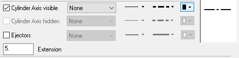
Cylinder Axis
The Cylinder Axis view attribute (see the View Attributes dialog above) enables the display of center lines automatically for all holes and shafts in a simple and section view. The Extension parameter defines the amount the center line "extends" both sides beyond the cylinder.
The defaults below are applied to the Cylinder Axis attributes. These defaults are defined in Preferences (Tools > Preferences > Drafting > Drawing and Sheet > View Attributes).
|
|
Cylinder Axis visible: Checked Cylinder Axis hidden: Unchecked Extension: 5 mm or 0.25 inch Pen: 1 Style: symmetry line (grayed out – cannot be changed) Color: black If the Model hidden attribute is not checked, Cylinder Axis hidden is grayed out (not checked). |
The Cylinder Axis attribute shows a symmetry line (with a defined extension) for every cylindrical and cone face in the model which is represented in the view by two lines. This symmetry line can be edited using the Symmetry Line function and dimensioned using the Symmetry Line Dimension dialog.
If a hole/shaft is not visible in the view, the related center line is also not visible.
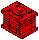
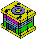
The definition of a cylindrical/cone face (to show a center line) is every cylinder/cone face in the model that is at least 180 degrees (or more). In the examples below, all the yellow faces will not get a center line (the round faces are 90 degrees and the other yellow faces are less than 180 degrees). All the green faces will get a center line in the view.
A split face in the model is recognized as one face (the examples below are valid and will get a center line).
|
For clarity, a single center line is displayed in cases where multiple center lines with the same direction may completely or partially overlap each other. In the example below, there are several holes/shafts with different depths and radii, however, only a single center line is displayed. |
The base length of the center line (without the extension) is according to the longest side (face boundary) of the cylinder. |
|
|
|
|
Editing View Attributes
Once the view attributes of a specific view have been defined, the View Attributes item in the Drawing tree can be edited, cut, copied or deleted by right-clicking on it, or dragged within the Drawing Tree to another view in any sheet in the file (see the image below).
A warning message is displayed and when approved, the target view is immediately displayed with the newly-applied view attributes.