![]()
Dynamic Section 

Access: Open this function from one of the following locations:
-
Select the Dynamic Section button
in the Interactive UCS toolbar. -
Select View > Views > Dynamic Section from the menu bar.
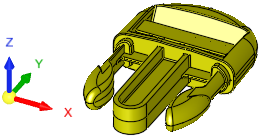
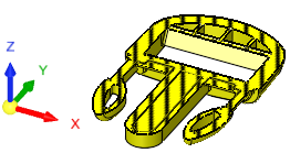
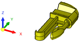
Dynamic Section creates a temporary section along a plane, which can be adjusted by moving a control in the Dynamic Section dialog.
|
Dynamic Section |
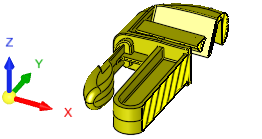
Dynamic Section - In use |
|
|
|
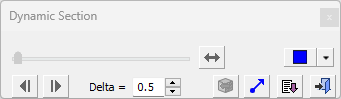
The Dynamic Section dialog is initially docked to the tree pane, above the top tree.
Dynamic Section dialog
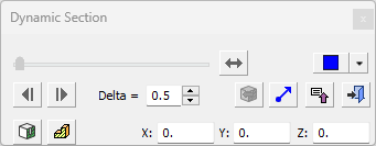
Dynamic Section dialog showing Advanced buttons
This dialog can be dragged anywhere on the desktop, the new location becomes the new default.
Defining the Section Plane
The Dynamic Section function displays a cross section through the assembly along a plane.
- If a start point is not selected, the view plane will not be created until a point or plane is selected.
- If a plane or a planar face is selected, it is used as the section plane. This can be changed by clicking the flip button, or by picking a point to display the direction arrow
- If a point is selected, the XY plane (normal to Z) is used as the section plane, but can be changed, by using the displayed direction arrow.
- If you reselect a point or plane while Dynamic Section is being used, the current Section Direction settings are used.
|
Use the slider to move the section plane. |
||||||||||||||
|
Click this button to flip the direction of the Dynamic Section.
|
||||||||||||||
|
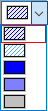
Hatch: Select the Hatch type
from the dropdown list
The default hatch type is defined in the Preferences. |
||||||||||||||
|
Use the backwards and forwards buttons to move the section plane by the incremental value set in the Delta field. |
||||||||||||||
|
Set the dynamic section incremental delta value when using the backwards and forwards buttons. |
||||||||||||||
|
Reload the most recent Dynamic Section configuration. |
||||||||||||||
|
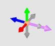
Set the section direction. This displays the direction arrow; set the required direction.
The section defaults to the Z direction. Use the Arrow button
The selected direction can be changed by clicking the Flip button Exit this mode either by clicking the MMBMMB, pressing ESC, or by making any selection on the dialog. |
||||||||||||||
|
Expand
Expand/Collapse: Expand the dialog to show the Advanced options. Collapse the dialog to hide them. |
||||||||||||||
|
Exit: Exit the operation and close the dialog/task. |
||||||||||||||
|
Save an M-view based on the view on-screen at the current section point in the document that is active at the time of creation. The M-View is named Dynamic M-viewX where x is the next available auto-number, and can be renamed in the M-view tab. |
||||||||||||||
|
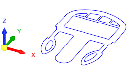
Create a section curve (wireframe of a section) from a dynamic section. For more on Section Curves, see From Face. Set the color of the section curve by selecting from the Use Active Color / Use Face Color toggle option. The default color for the section curve is defined in the Preferences. The wireframe will appear in the Feature Tree as a Section Curve feature. Thisonly exists inside Dynamic Section function, the section curve does not exist in the wireframe menu.
The section curves cannot be edited, but they can be deleted or renamed. You can select these section curves on the screen like any other wireframe, by using either the composite or curve Selection Filter.
The most recent Section Curve can be reloaded to use as the Dynamic Section. |
||||||||||||||
|
These fields allow you to set the precise location of the section plane before creating the section curve. |
||||||||||||||


When you are finished, press Exit ![]() in the dialog to complete the function.
in the dialog to complete the function.
When completed, if a section curve was not created (if only a dynamic section was created), the Feature Tree is not changed.