Ejector Lock  : Options and Results

Access: Open this function from one of the following locations:
-
Select Mold Design > Ejection > Ejector Lock from the menu bar.
-
Select Ejection > Ejector Lock from the Mold Design Guide Toolbar.
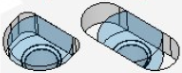
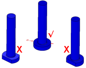
Create a lock shape on ejectors and cutting objects. This function detects ejectors that need to be locked to prevent their rotation in the ejector plate and modifies the ejector head and the ejector cutting object according to the required lock type to create the appropriate pocket on the plate.
For example:
Note: It is recommended to run this function after Ejector Trim is used and before Ejector Pocket is executed.
Different types of Ejector Locks may be used. The following are examples of the various types of Ejector Locks.
|
|
|
|
|
|
Pin Lock |
Oval Lock |
Circle Lock |
Slot Lock |


Ejector locks can be created globally on all ejectors (with different diameters) or just on selected ejectors. The ejector lock type and rotation angle can be changed locally.
An Ejector Lock Type attribute is assigned to each ejector after a lock has been added. This attribute is used in the Table of Ejectors and the BOM Table.
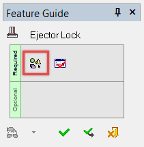
Required Step 1 
InvokeInvoke the Ejector Lock function.
Note: Cimatron automatically identifies and highlights the ejectors that require locking, thereby bypassing the Feature Guide's Required Step 1 and advancing to Required Step 2.
In the event that not all ejectors are automatically selected as needed, pickpick the Required Step 1 button (Pick Ejector(s) to Make a Lock) in the Ejector Lock Feature Guide to select additional ejectors as needed.
Note: Hover the mouse cursor over any unselected ejector(s) to display a tooltip that indicates why the ejector was not selected. For more information, see the Ejector Lock Analysis Rules.
The following toggle parameter appears in the graphics window. The available options are Auto + Free Selection or Same Head Diameter Only. Select the appropriate option as needed.
|
|
|
|
|
Auto + Free Selection |
When the Auto + Free Selection option is selected, the system automatically starts analyzing ALL ejectors (under the current Ejector subassembly) based on specific analysis rules and then selects the relevant ejectors. See the Ejector Lock Analysis Rules below. The user can add valid ejectors for locking or remove selected ejectors from the automatic selection by manually picking or unpicking them. This option is automatically performed when invokinginvoking this function and the system proceeds to Required Step 2 of the function. |
|
Same Head Diameter Only |
When manually switching to Same Head Diameter Only, the selection performed by the Auto + Free Selection option will be cleared and you can select ejectors that are not selectable under the automatic analysis of the Auto + Free Selection option (such as ejectors with a trim with a flat top).
If no ejector is selected, the selection by box will analyze all ejector head diameters and will pick the ejectors with the largest number of same head diameters, while other ejectors will be rejected.
If, after selecting one or more ejectors with the same head diameter you single pick an ejector with a different head diameter, a message is displayed informing you to pick an ejector with same head diameter.
|
Ejector Lock Analysis Rules
When the Auto + Free Selection option is selected, the system automatically starts analyzing ALL ejectors (under the current Ejector subassembly) based on specific analysis rules and then selects the relevant ejectors.
The analysis performed automatically (in Required Step 1) is based on the following rules.
Note: The colors depicted below, YELLOW and BLUE, are the colors that will be assigned to the ejectors in Required Step 2 of the function. In addition, a tooltip is displayed for each ejector when hovering the mouse cursor over the ejector.
Ejectors that are LOCKED are not automatically selected. This includes:
Ejectors that already have an ejector pocket.
Special ejectors where the ejector head is not a full cylinder.
Example:Example:
Ejectors that have already been analyzed and selected by the Ejector Lock function.
Ejectors that are LOCKED are not usually needed (by default they are not selected, as mentioned in item 1 above); however, the following ejectors may be manually selected:
Ejectors (with a circular profile) after being trimmed with a FLAT top.
Example:Example:
|
|
|
|
Shaped Trim |
Flat Trim |
Ejectors that have an ejector blade type after being trimmed with a FLAT top.
Example:Example:

Non-Symmetrical Ejectors: These are colored YELLOW. Any type of lock can be applied to Non-Symmetrical Ejectors, except a Slot Lock.
A Non-Symetrical Ejector is defined as one where (after being trimmed and then rotated by 180°) the result is not perfectly matched to the ejector before the rotation.
Additional examples of non-symmetrical ejectors are:
Ejectors that have not been trimmed (in this case a Slot Lock is not an option).
Ejectors that have a blade type after being trimmed with a SHAPED top.
Example:Example:
These will not be selected by default. You can select them but they will not get a Slot lock and, hence, are colored YELLOW in Required Step 2 of the function.
|
|
|
|
Shaped Trim |
Flat Trim |
Symmetrical Ejectors: These are colored BLUE and any type of lock can be applied to them. A Symmetrical Ejector is defined as one where (after being trimmed and then rotated by 180°) the result is perfectly matched to the ejector before the rotation.
In each of these cases, an appropriate message is displayed to prompt you with your selection.
After the analysis is completed, you will be able to unselect (and reselect) ejectors. When picking one or more ejectors that were created with instances, the selection (or unselection) is applied to all the instances.
Note: To have different lock types for different instances, run the Instance to Part function first.
Required Step 2 
PickPick the Define Lock Type and Rotation Angle button in the Ejector Lock Feature Guide to display the Ejector Lock dialog.
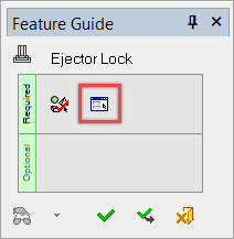
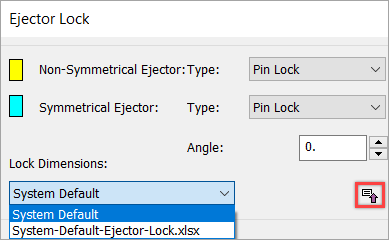
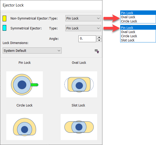
Navigate to the Ejector Lock dialog to specify the ejector type and the rotation angle.
Expand or collapse the dialog to show or hide additional information.
| Ejector Lock dialog collapsed | Ejector Lock dialog expanded |
|
|
|
Parameters
|
Non-Symmetrical Ejector |
Select the lock type for the Non-Symmetrical (YELLOW colored) ejectors from the following dropdown list of types: See the expanded dialog above for example images of the various lock types. |
||||||
|
Symmetrical Ejector |
Select the lock type for the Symmetrical (BLUE colored) ejectors from the following dropdown list of types: See the expanded dialog above for example images of the various lock types. |
||||||
|
Angle |
Set the rotation angle of the lock. See the Angle examples in Preview below. |
||||||
|
Lock Dimensions |
From the dropdown list, select the lock dimensions to be used to create the ejector lock features. The following options are available:
|
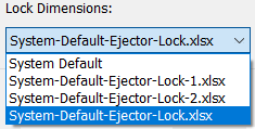
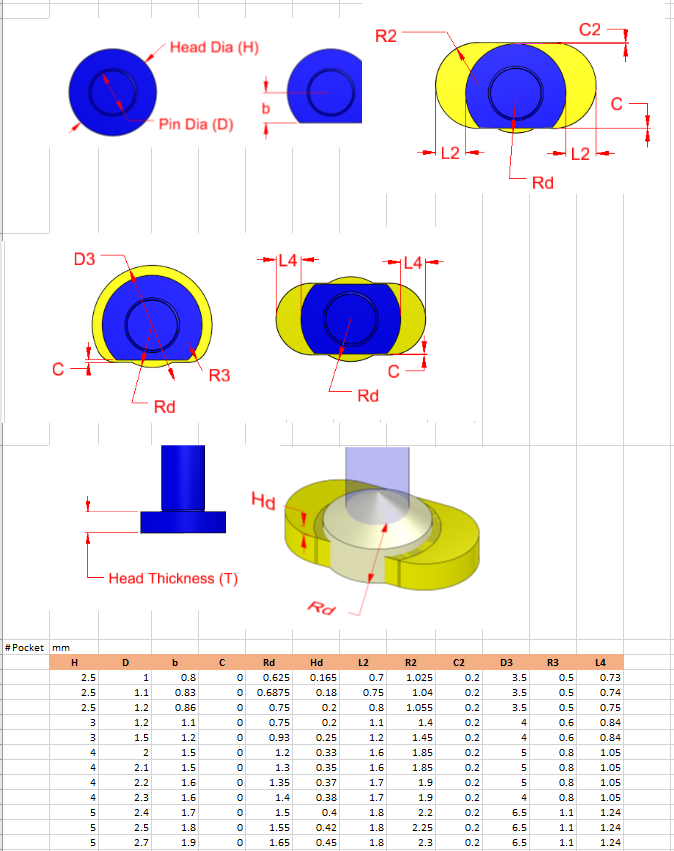

See Preview and Local Modification below.
Buttons
The following buttons are in the dialog
|
|
Expand or collapse the dialog to show or hide additional information. Expand |
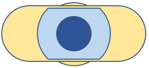
Preview
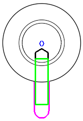
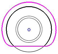
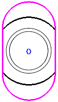
While in Required Step 2 of the function, any change of the ejector lock type and/or angle in the Ejector Lock dialog is displayed in wireframe form in the graphics window.
|
|
|
|
||
|
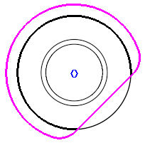
Pin Lock = 0° |
|
Circle Lock = 0° |
|
Slot Lock = 0° |
|
|
|
|
||
|
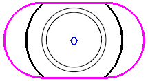
Pin Lock = 45° |
|
Circle Lock = 45° |
|
Slot Lock = 90° |
Preview: Collision Detection
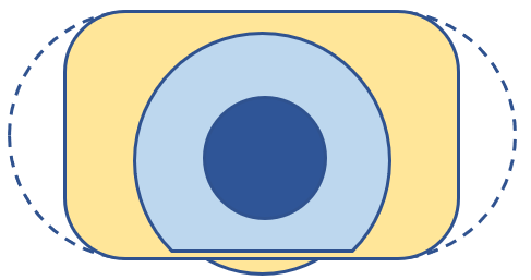
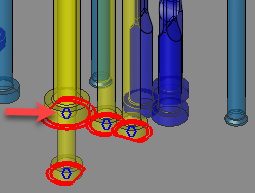
An ejector lock highlighted in RED (as shown below) indicates that a collision has been detected where the ejector head intersects with the newly created pocket.

To remediate a collision:
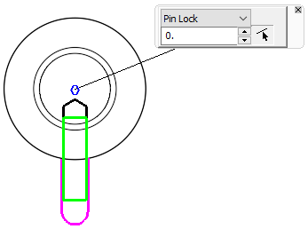
PickPick the BLUE POINT inside the RED highlighted area.
The local parameter dialog (shown below) appears in the graphics window. Adjust the ejector lock's type or rotation angle as necessary. See Local Modification below for more information.

Note: The ejector lock collision indication is only a warning and does not prevent the execution of the Ejector Pocket operation.
Local Modification
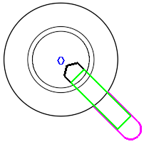
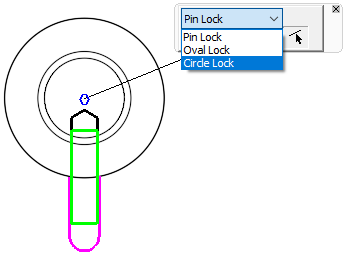
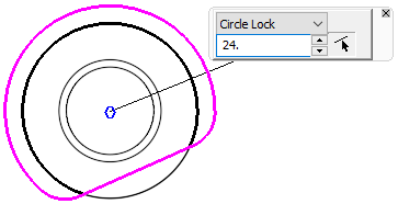
Local changes may be made to ejector lock types and/or rotation angles from the graphics window. Select an ejector with a lock type to display a local dialog with parameters to change the selected ejector lock. The local ejector lock type can be changed from the local parameter's dropdown type list.
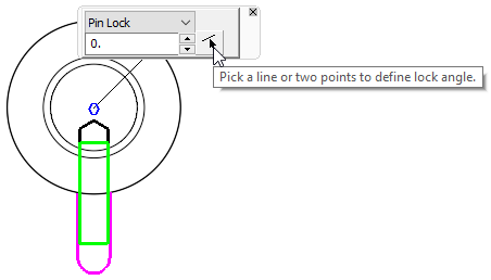
The local ejector lock rotation angle can be changed by either entering the required angle in the angle text box or by clicking the button adjacent to the angle text box and picking a line or 2 points to define the lock angle.
|
|
|
|
Ejector lock local change parameters |
Ejector lock local change lock types |
|
|
|
|
Ejector lock changed locally by editing the angle text box |
The local angle of the ejector lock can be changed by selecting 2 points to define the lock angle |
When you select OK ![]() or Apply
or Apply ![]() in the Feature Guide to complete the function, the Ejector Lock feature will appear in the Feature Tree as follows:
in the Feature Guide to complete the function, the Ejector Lock feature will appear in the Feature Tree as follows:
