|
|
Swarf by Contours > Multi Cuts
The Multi cuts tab is displayed.
This tab enables you to set the pattern slicing and machining parameters for multiple cuts.
To display additional parameters, click the relevant tab in the dialog image below.
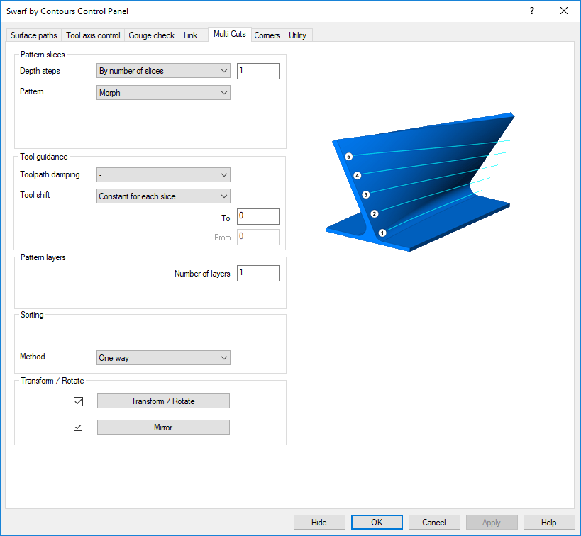
Tabs
Animations below may be shown automatically or by clicking the movie prompt image (like the demonstration image shown below):

Depth steps
The pattern slices can be set to single slices and multiple slices. Aim is to be able to swarf cut the machining area with multiple step depths in case the tool flute only has a short length.
The single slice will generate a single slice at the lower curve. Make sure that the flute length is sufficient.
Multiple Slices
The multiple slices will generate multiple slices between the 2 curves. The slices can be defined by a maximum distance, where you have to provide a step distance, or by a maximum determined number. The picture shows a total number of 5 slices.
The multiple slices are copies of the initial slice. The 'copy' direction will can be defined by 2 directions. They can either be along the tool axis or along the contact line. In case that a conical tool is being used, a retraction along the tool axis is not applicable. The tool would leave the surface in the upper cuts due to the conic angle. In this case the option 'contact line' should be used.
Note that the multiple slices are equidistant between the upper and the lower curve.
Pattern
There are 3 pattern available, step from bottom, step from top and morph.
The aim is to control how the tool should proceed with the multiple depth steps on the swarf area.
Step from bottom
Here all cuts are parallel to the lower curve
Step from top
Here all cuts are parallel to the upper curve
Morph
Here the cuts morph between the upper and lower curve

Direction
This setting applies only for conical tool shapes. The tool can retract into tool axis direction or tool contact line when performing the depth steps.
The animation shows the retraction along the tool axis. You see that the upper cuts are located off the swarf surface. That means that as the tool proceeds in the machining, the material will be removed from top town as well as from outside to inside.
Contact line
When selecting the contact line then the conical tool always is in contact with the actual swarf surface. The material will be machine only from top down.
Layers
The pattern layer can be set to single layers and multiple layers. The aim is to be able to create offset layers from the pattern slices in case the material can't be cut in only one layer.
The single layer will leave the slices as they are.
Multiple Layers
The multiple layers will generate multiple offset layers from the slices. The layers will be defined by a maximum distance, where you have to provide the offset distance and the number of layers. The pictures shows 5 slices with 2 layers.
Tool Shift
Constant for each slice
The axial shift will be applied with a constant value for each slice
Gradual for each slice
The aim here is to shift the tool tip point with every new slice a little bit deeper. For this the user has to specify a start value (from) and an end value (to). The axial shift will be gradually added to every slice.
In the animation you see that the tool start almost at the top of the surface. The final cuts though is shifted much deeper.
Method
One way
One way lets the tool always start over from the same side
Zig Zag
Zig Zag alternates the direction as the tool proceeds.
Sequence
By slice
This sequence machines at first the upper slices steps down after. For example;
- Slice 1 Layer 1
- Slice 1 Layer 2
- Slice 2 Layer 1
- Slice 2 Layer 2
By layer
This sequence will machine layer by layer. For example;
- Layer 1 Slice 1
- Layer 1 Slice 2
- Layer 2 Slice 2
- Layer 2 Slice 2
|