|
|
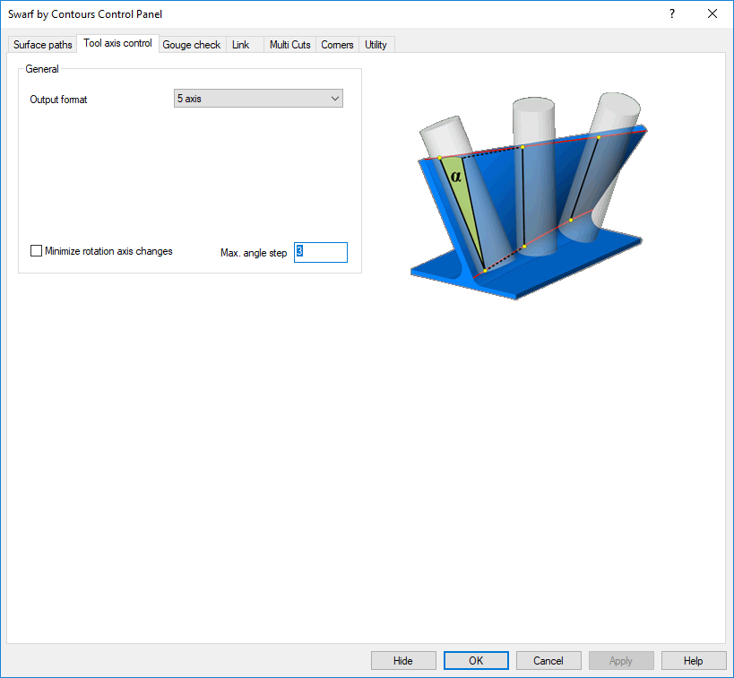
Swarf by Contours > Tool Axis Control
The Tool axis control tab is displayed.
This tab allows you to define the tool orientation relative to the surface normal. You can set machining limit angles and define the contact point between the tool and the surface.
To display additional parameters, click the relevant tab in the dialog image below.
Tabs
Animations below may be shown automatically or by clicking the movie prompt image (like the demonstration image shown below):

Max. angle step
The animation shows a machining with standard angle change of 3 deg.
This animation shows the same tool path. Here an angle change of 1 deg. is used. You see that more points needed to be calculated.
Minimize rotation axis changes
This feature will avoid that the tool runs into singularity problems so that strong machine movements will be minimized.
The animation shows the option activated. Tilting is smooth along the surface.
Option deactivated
The animation shows the option deactivated. You see that the C axis rotates very fast when the tool is in the center of the machine.
Damp
It is now possible to apply axial damping to the tool while swarfing along the wall. The main benefit is present when the upper or lower input curve is not tangent and has sharp corners that would cause the tool to immediately retract or plunge.
The animation shows a swarf machining of a wall with a non tangent lower curve. Without damping the tool axis will follow the curve's shape. This forces the tool to axially plunge onto the drive surface.
With the damping activated we get a smoother motion on that area.
Fanning distance
The fanning distance can only be used for the strategy 'Shortest distance'.
Here tool tends to stay vertical between the 2 curves for the straight areas. When the upper and lower curve have different length, then the tool stops at the end point of the shorter curve and only continues moving with the tool tip. We call that fanning. To avoid that the tool stops at the shorter curve, the user can set a fanning distance.
The animation shows a good example. The tool stays vertical on the flat areas, you see that the tool stops in the corner and does the fanning. The fanning distance is 0, that means the tool basically stops at one end of the curve.
The animation shows the tool path with a bigger fanning distance. You can see the tool blending into the corner before it reaches the end of the curve.
Swap curves
Here the aim is to be able to swap the curves for the automatic curve detection for swarf machining. In some case the system assigns the curves not in the way the user would like to have them.
|