|
|
Extend and Cap: Options and Results
Select a tangent or vector to form a surface that terminates a dip or bump in a parting line or die binder that brings the shape back down to the main working plane. Surfaces are created from the selected contour in a specified direction, maintaining the original topology and surfaces directions.
Required Step 1
-
Click to pickClick to pick the contour that will be used for the feature. The contour must be either a Composite Curve or a Sketch feature to ensure there are no large gaps in the selected contour. The contour must contain more than one segment.
- Select the method to use to create the faces. There are two options;
-
Tangent—Create extensions continuous with the faces whose edges were selected. These extensions are always new faces. For more, see Extend (Face):Tangent > Continuous. This option is only available when faces can be detected and used to determine tangency.
-
Vector—Create a face by sweeping a curve, edge, contour, or sketch in a specified direction. For more, see Sweep.
-
-
ExitExit to proceed to Required Step 2.
Required Step 2
-
Use this step to define the parameters.
Selected Method Options Vector Sweep the selected geometry on one or both sides, by a given value and direction.
- By Delta - Set the distance to extend the faces
- By Reference - The curve is extended to a selected reference geometry (face, edge, curve, point, or datum), either to the intersection point of the two geometries or if intersection is not possible, to the point of the Normal line between the extension and the reference.
Note: If the bump or dip extends at an angle to the mating face, the shortest faces in a selection are extended until all faces reach a plane that is normal to the vector.
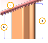
a Parent part b Delta or reference length c Extended length Tangent Create the extension continuous with the faces whose edges were selected. These extensions are always new faces (This option is only available if source faces can be determined from the selected contour).
- Delta length - Set the distance to extend the faces
- Flip - Flip the extension direction
Note: The default offset side is outside for a closed reference contour and according to the curve direction for an open reference contour.
-
Select which method to use to seal off the end of the feature―Options are Angled or Rounded:
Selected Method Options Angled
The endpoints of the outermost edges that describe lowest plane for a bump or the uppermost plane for a dip are used to determine a build plane. The angled end is calculated and created from perpendicular to this plane.
-
Draft Angle: Select the angle to assign to the end plane of the new feature
-
Radius Value: Select the radius to apply to the top edge of the new feature
Rounded A 3 tangent arc is created between the 2 outermost edges and a connecting line. Edges that do not sit on the working plane are projected onto it to create the radius. The arc is used as the path to drive a face matching the profile of the bump or dip. -
Optional Step 1
-
Trim Underlying Faces: Underlying geometry to the faces being extended and capped (binder or parting faces) are trimmed to prevent features in multiple trees. Only faces in the active part can be selected in the optional step.
Click MMB to exit the step when complete.
The surface plane at the maximum extent of the dip or bump is projected to cap the new feature and all faces are stitched. A status alert shows when the feature has completed. Any problems in the creation of the feature of issues with the result are displayed in the Conflict Solver dialog.
-
Complete: The feature was successfully created and no problem areas were highlighted
-
Partial: If the Complete result is unsatisfactory, use this option to view the minimum acceptable geometry showing the extended faces from the selected curves/composite, and then edit the underlying geometry to attempt to rebuild before re-submission.
|