|
|
Drawbead: Options and Results 


Access: Open this function from one of the following locations:
-
Select Die Design > Geometry Manipulation > Drawbead from the menu bar.
-
Select Geometry Manipulation > Drawbead from the following Die Design Guide: Die Process Design Guide (Forming).
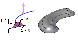
Create drawbeads to control material flow into the die cavity, forcing stretching and limiting cracking and wrinkling in the stamped part.
Required Step 1 
-
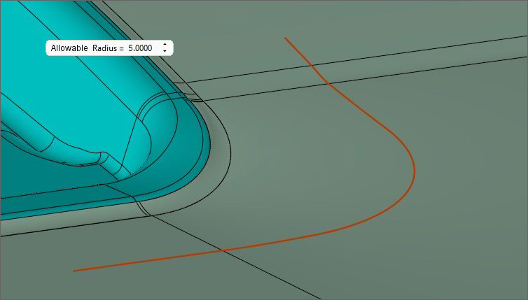
Click to pickClick to pick the curve (open or closed) that will be the trajectory/centerline for the Drawbead.
-
Select the Allowable Radius screen parameter to define the allowable radius value. (See the Parameters table below for a complete list of parameters available for this function and their definitions.)
-
ExitExit to proceed to Required Step 2.
Required Step 2 
-
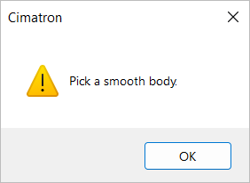
PickPick a smooth binder object.
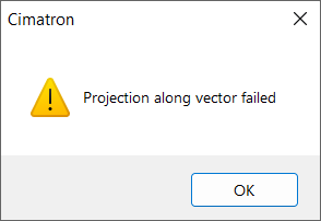
If you do not select a smooth body for the binder object the following message appears, you can continue without selecting a smooth body. Click OK to continue.
-
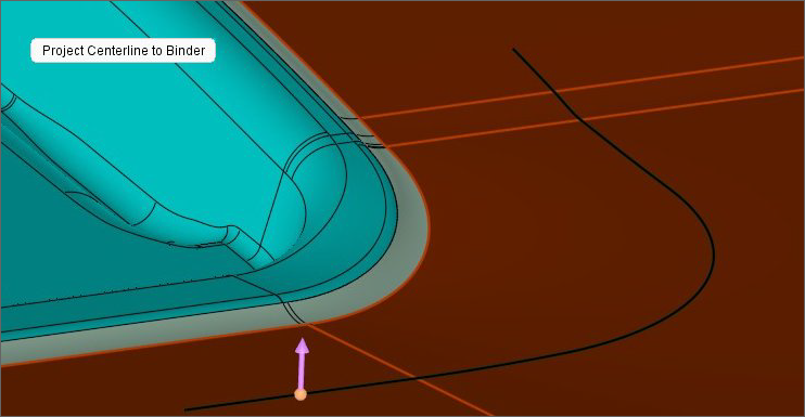
Go to the Project Centerline to Binder parameter. You can toggle this parameter to either project the centerline to the binder or not project the centerline to the binder. (See the Parameters table below for a complete list of parameters available for this function and their definitions.)
-
If the Project Centerline to Binder option is selected, a direction arrow is displayed. Use the arrow to control the projection direction if needed. If you select Don't Project Centerline to Binder, no further action is required. Proceed to Required Step 3.
Required Step 3 
Use this step to define the Drawbead dimensions. You can also make the Drawbead ends taper down.
Defining the Drawbead dimensions
-
Click the Required Step 3 icon
in the Drawbead Feature Guide. -
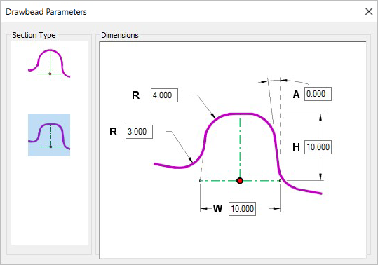
The Drawbead Parameters dialog is automatically displayed.
-
Select a Section Type (Full Round or Rounded Rectangle) and enter the Dimensions values as needed. (See Show Dialog in the Parameters table below for more information on the Drawbead Parameters dialog.)
-
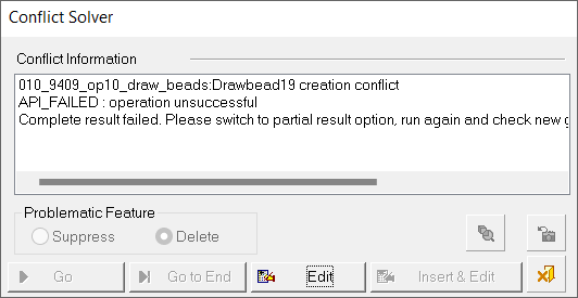
Next, toggle the Complete Result / Partial Result screen parameter to the appropriate option.
Selecting ends to taper down
Material can overstretch or tear at the Drawbead's ends; therefore, it is recommended that each end be tapered down.
-
Pick one or both end points of an open curve.
Note: The flip arrow that is displayed is for visual reference and cannot be adjusted.
-
The Tapered End Off screen parameter appears. Click on it to display the H Drop and Distance parameters.
-
Enter values for H Drop and Distance. (See the Parameters table below for a complete list of parameters available for this function and their definitions.)
-
Click OKOK
 or ApplyApply
 in the Feature Guide to complete the function.
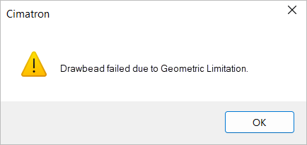
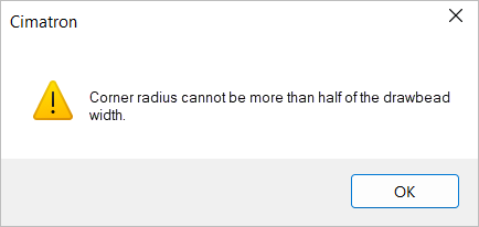
If Cimatron encounters an issue with any values defined in Required Step 3, the following error message appears.
Click OK and return to Required Step 3 to modify values as needed.
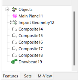
When the function has been successfully executed, the Drawbead feature will appear in the Feature Tree.
Parameters
|
Allowable Radius |
The allowable radius of the centerline. The default value is 5mm or .250 inches. |
||||
|
Complete Result / |
|
||||
|
Distance |
Defines the length of the transition distance along the curve until the H dimension is back to the general height value. This value must be a positive number. The default value is 40.0mm or 1.50 inches. |
||||
|
H Drop |
The distance to decrease the section height at the very end of the Drawbead curve. The value entered must be a positive number and not exceed the H dimension value. |
||||
|
Project Centerline to Binder / |
Toggle option that allows you to project the curve to the binder surfaces or not.
|
||||
|
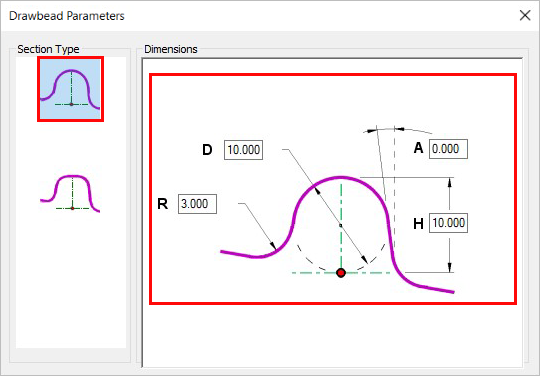
Click this parameter to show the Drawbead Parameters dialog. To close the dialog, either click the Show Dialog screen parameter or click the X icon in the top right corner of the dialog. The following images show the dialog as it appears for each Section Type selected (Full Round or Rounded Rectangle). The Drawbead Parameters dialog with the Full Round section type selected.
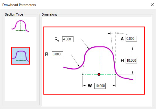
The Drawbead Parameters dialog with the Rounded Rectangle section type selected.
|


|