Hole: Options and Results - By Screw Size
Use this option to populate the available screw standards and sizes with data in Cimatron's thread list, which is stored in the system data/threads.csv file.
|
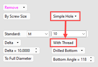
Simple Hole |
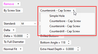
Define the shape of the head of hole. For each type of hole selected, set the appropriate parameters.
The dropdown options are: Simple Hole (for holes without heads), Counterbore – Cap Screw, Countersink – Cap Screw, and Counterdrill – Cap Screw holes: Images of each hole type:Images of each hole type:
|
||||||||||||||
|
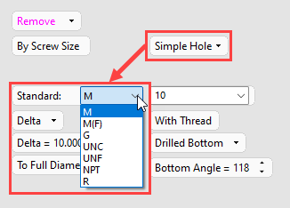
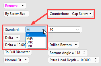
Standard |
Select the thread standard to use in the hole.
The thread standard associated with each option are shown below:
|
||||||||||||||
|
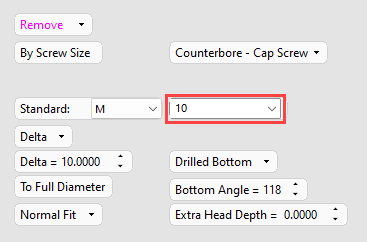
Thread size |
Select the thread size from those available for the selected thread standard.
|
||||||||||||||
|
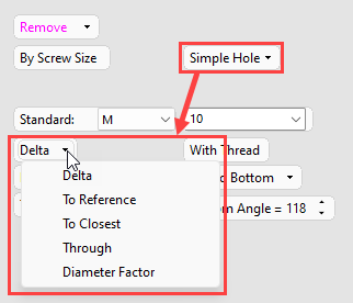
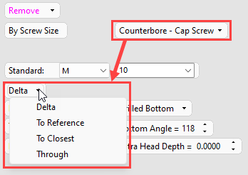
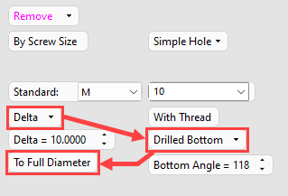
Delta |
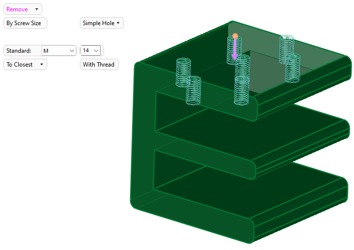
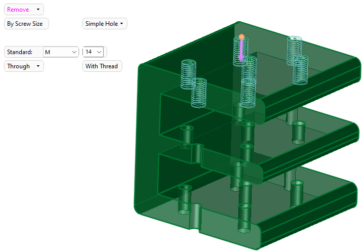
Select a setting to define the hole depth from the dropdown list:
|
||||||||||||||
|
With Thread Visible when:
|
Create a threaded simple hole. Toggle the option to Without Thread for a simple hole with the correct tap drill size.
|
||||||||||||||
|
To Full Diameter Visible when:
|
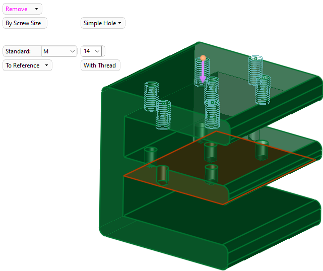
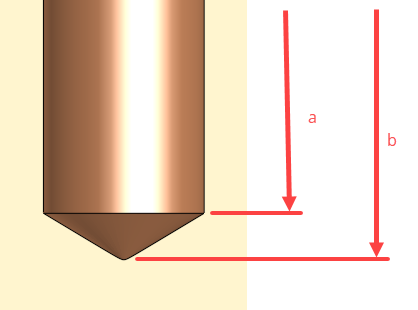
Select an option to define the point at which the hole delta is measured.
The points defined by the two options are shown below:
a) To Full Diameter b) To Drill Tip |
||||||||||||||
|
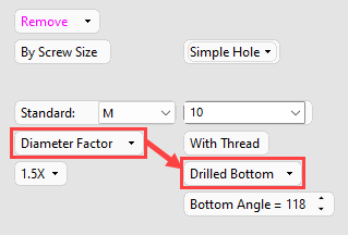
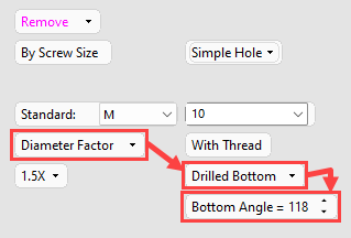
Drilled Bottom Visible when:
|
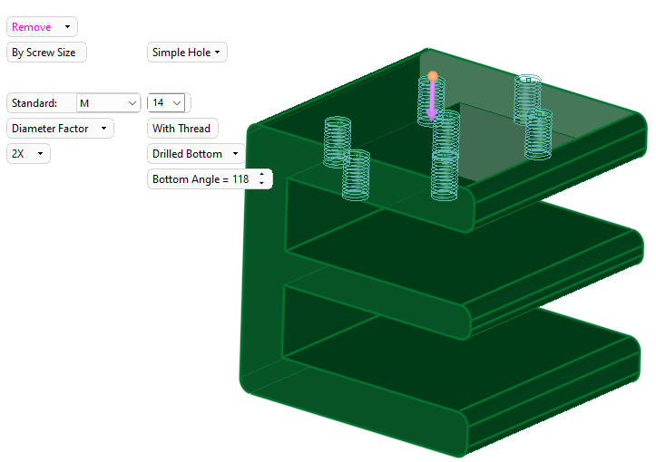
Select an option to define the shape of the bottom of the hole.
|
||||||||||||||
|
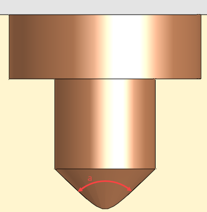
Bottom Angle Visible when:
|
You can adjust the bottom angle by selecting any value between 0 and 180 degrees.
a. Bottom Angle
|
||||||||||||||
|
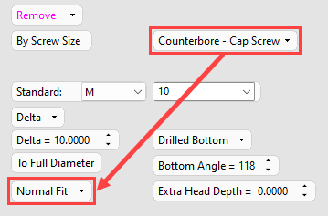
Normal Fit Visible when:
|
The fit can configured for countersunk, counterbored, and counterdrilled holes (fit values obtained from the threads.csv file). Select from Normal, Close, and Loose.
|
||||||||||||||
|
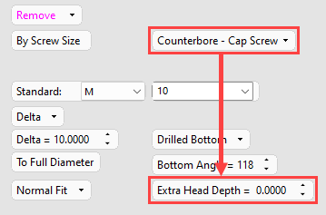
Extra Head Depth Visible when:
|
The depth at which the head of counterbored and counterdrilled holes is recessed below the surface can be increased or decreased from the system value (obtained from the threads.csv file) by the specified amount. Countersunk holes do not have a default value; This value can be positively adjusted to increase the Head Diameter value - negative values are not permitted for countersink holes.
|
||||||||||||||
|
Invert Active Object |
Use the Invert Active Object option as required. This parameter is available only for open objects and deals with issues of object direction. |
Optional Step 1 
Change the active object. This option is only available in the following cases:
-
when creating a feature. The option is not available when editing a created feature.
-
if there is more than 1 object in the active part.
A toggle parameter is displayed; Keep Original Active Object / Activate Selected Object.
|
Keep Original Active Object |
Keep the active object originally used in the function. |
|
Activate Selected Object |
Change the active object to the selected object. Pick an object as required. |
When you have set the diameter, depth, and head parameters (Counterdrilled, Counterbored, and Countersunk holes), click OK ![]() or Apply
or Apply ![]() in the Feature Guide to complete the function.
in the Feature Guide to complete the function.
When completed, the Hole feature will appear in the Feature Tree as follows: