|
|
Measurement  : Distance

Select the ![]() Measuring
button or select Analyze/ Measurement
from the menu bar.
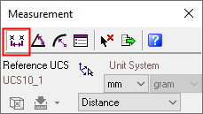
From the displayed Measurement
dialog click the Distance
Measuring
button or select Analyze/ Measurement
from the menu bar.
From the displayed Measurement
dialog click the Distance
![]() button.
button.
Cimatron provides various combinations for measuring distances. Examples include the distances from Axis to Plane, Line to Face, Face to Face, Object to Face, Curve to UCS and so on.
The Measurement dialog is displayed. Click the Distance ![]() button.
button.
|
|
When switching between measurement types, the system automatically displays the last measurement type in the current measuring session. For example, if you use the |

Some examples for measuring distance, described in this Help are displayed, as follows:
-
Measuring Lines: Finding the Nearest Point (Using Multi Point Selections)
-
Measuring Arcs, Circles and Ellipses: Diameter and Radius Measurements
Note: When selecting multiple entities (such as, axis to plane, line to point, face to line and so on), the system will always display the shortest distance between two selected entities, apart from measuring the distance between two axis and two planes.
Measuring Points: Distance from UCS to Point
Select any point. A line is automatically created between the point and the active UCS, as follows:
|
|
|

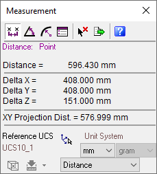
The Measurement dialog displays the following information:
|
|
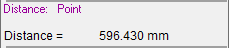
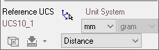
Primary Data Area: |
|
|
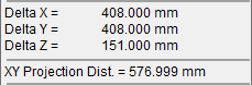
Secondary Data Area: See Differences between "Distance", "XY Projection Dist." and "Display Plane Dist.". |
|
|
Advanced Area: Change the defaults if applicable. |
Measuring Lines: Distance Between Two Points
Select two points. A line is automatically created measuring the distance between the two points, as follows:
|
|
|
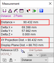
Differences between "Distance", "XY Projection Dist." and "Display Plane Dist."
See the examples below.
|
Distance |
The distance between the selected points. |
|
XY Projection Dist. |
The projected distance between the selected points on the XY plane. |
|
Display Plane Dist. |
The current screen distance between the selected points, when measuring 2 points. |
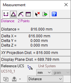
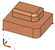
In the example below, the Distance and the XY Projection Dist. are the same. This is because the distance being measured is actually on the XY plane (Delta Z = 0 mm).
Note the Display Plane Dist..
|
|
|
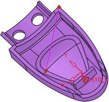
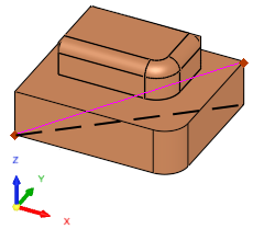
In the next example below, the Distance and the XY Projection Dist. values differ as they are not on the same plane (Delta Z = -20 mm). In this case, the black dashed line represents the XY Projection Dist..
|
|
|
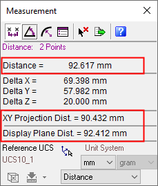
Measuring Lines: Finding the Nearest Point (Using Multi Point Selections)
You can measure the minimum or maximum distance between many points by selecting the required option from the Distance dropdown list in the Advanced Area, and then performing multi point selections. In the example below, the Minimum Distance option is chosen and a number of points selected. In this case, the system displays the shortest line between the points.
|
|
|

Measuring Arcs, Circles and Ellipses: Diameter and Radius Measurements
Select an arc, circle or ellipse. The system automatically measures and displays the radius and diameter of the entity.
|
Arc: |
Circle: |
|
|
|
|
Ellipse: |
|
|
|
|