|
|
Simulation Properties
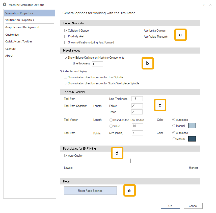
The Machine Simulator Options dialog contains options related to the simulation.
-
Popup Notifications
Use these options to pause the simulation and display notification windows when the following events occur:
- Collision & Gouge: when collisions or gouges occur in the simulation.
- Proximity Alert: when the tool, stock or machine components are closer to each other than the allowed threshold.
- Axis Limit Overrun: when a linear or rotational axis exceeds its specified upper or lower limits.
- Axis Value Mismatch: when an axis value/position is not within the allowed values.
- Show notification during Fast Forward: enable popup notifications to occur during fast-forward.
Notes:
- None of these options prevent the Machine Simulator from reporting any of the problems encountered in the Report docking pane.
- When Yes checkbox is marked in any of the popup notification messages (and Don't show again checkbox is unmarked) the popup will not appear again when the subsequent moves encounter the same problem. The popup appears again only when the group of consecutive moves with the same issue has been processed and another move with problems is encountered.
- There are 2 ways to disable the popup notifications:
- ...in this simulation: In the background, the status of the Popup Notifications checkbox changes (either to completely unmarked or semi-selected) and the respective popup will not appear any more during the entire simulation nor during subsequent simulations (after the Machine Simulation has been restarted). To revert this behavior, the user must change the respective checkbox in the Popup Notifications.
- ...in this operation: There will be no change in the Popup Notifications checkbox. The checkbox reverts to its original status when the user goes/jumps to another operation.
-
Collision & Gouge category
When the popup notification appears, the simulation is paused and the following options are available:
-
No keeps the simulation paused and closes the popup message.
-
Yes (default button) has the following behaviors:
-
When Do not show again checkbox is unmarked, it allows the simulation to resume.
-
When Do not show again is marked and:
-
for all gouges and collisions checkbox is marked, the simulation resumes, the Collision & Gouge checkbox is automatically deselected, and the Gouge/Collision popups will not appear any more.
-
for all similar events in this operation checkbox is marked, the simulation and the Gouge/Collision popups will not appear any more for the mentioned event type until the simulation reaches the next operation/sub-operation or the Restart button is clicked. The popups for the respective event type will then appear again.
-
for all similar events in this simulation checkbox is marked, the simulation resumes, the Collision & Gouge checkbox is semi-selected and the Gouge/Collision popups will not appear any more for the mentioned event type.
-
for this pair in this operation checkbox is marked, the simulation resumes and the Gouge/Collision popups will not appear any more for the named pair in the message (bold elements) until the simulation reaches the next operation/sub-operation or the Restart button is clicked. The popups for the respective pair will then appear again.
-
for this pair in this simulation checkbox is marked, the simulation resumes, the Collision & Gouge checkbox is semi-selected and the Gouge/Collision popups will no longer appear for the named pair in the message (bold elements).
-
-
Note: To re-enable popup notifications when the options for all gouges and collisions or in this simulation were used from the Do not show again drop-down, mark the Collision & Gouge checkbox again.
Notes:
Events Types:
-
geometry vs. geometry collision (where the geometry is not a tool or stock object)
-
* tool flute vs. workpiece gouge
-
* tool flute vs. workpiece collision
-
* tool flute vs. geometry collision (where the geometry is not a stock or workpiece object)
-
* tool shaft vs. geometry collision (where the geometry is not a stock object)
-
* tool arbor vs. geometry collision (where the geometry is not a stock object)
-
* tool holder vs. geometry collision (where the geometry is not a stock object)
-
stock vs. geometry collision (where the geometry is not a stock object) (appears only when Material Removal mode is active)
-
tool flute vs. stock collision (appears only when Material Removal mode is active)
-
tool shaft vs. stock collision (appears only when Material Removal mode is active)
-
tool arbor vs. stock collision (appears only when Material Removal mode is active)
-
tool holder vs. stock collision (appears only when Material Removal mode is active)
(*) works only when Collision Detection Settings: Report Collisions for Tool Parts is active (see File - Info. If not, the following grouping applies:
- 2=3=tool vs. workpiece collision
- 4=5=6=7=tool vs. geometry collision (where the geometry is not a stock or workpiece object)
-
-
Proximity Alert category
When the popup notification appears, the simulation is paused and following options are available:
-
No keeps the simulation paused and closes the popup message.
-
Yes (default button) has the following behaviors:
-
When Do not show again checkbox is unmarked, it allows the simulation to resume.
-
When Do not show again checkbox is marked and the option:
-
for all proximity alerts checkbox is marked, the simulation resumes, the Proximity Alert checkbox checkbox is unmarked and the Proximity Alert popups will not appear any more.
-
for all similar events in this operation checkbox is marked, the simulation resumes and the Proximity Alert popups will not appear any more for the mentioned event type until the simulation reaches the next operation/sub-operation or the Restart button is clicked. The popups for the respective event type will then appear again.
-
for all similar events in this simulation checkbox is marked, the simulation resumes, the Proximity Alert checkbox will be semi-selected and the Proximity Alert popups will not appear any more for the mentioned event type.
-
for this pair in this operation checkbox is marked, the simulation resumes and the Proximity Alert popups will not appear any more for the named pair in the message (bold elements) until the simulation reaches the next operation/sub-operation or the Restart button is clicked. The popups for the respective pair will then appear again.
-
for this pair in this simulation checkbox is marked, the simulation resumes, the Proximity Alert checkbox will be semi-selected and the Proximity Alert popups will not appear any more for the named pair from the message (bold elements).
-
-
To re-enable popup notifications when the options for all proximity alerts or ... in this simulation were used from the Do not show again drop-down, select the Proximity Alert checkbox again.
Events Types:
-
geometry vs. geometry alert (where the geometry is not a tool or stock object)
-
stock vs. geometry alert (where the geometry is not a stock object) (appears only when Material Removal mode is active)
-
tool shaft vs. stock alert (appears only when Material Removal mode is active)
-
tool arbor vs. stock alert (appears only when Material Removal mode is active)
-
tool holder vs. stock alert (appears only when Material Removal mode is active)
-
tool shaft vs. workpiece/fixture (table) alert
-
tool arbor vs. workpiece/fixture (table) alert
-
tool holder vs. workpiece/fixture (table) alert
-
-
Axis Limit Overrun category
When the popup notification appears, the simulation is paused and following options are available:
- No keeps the simulation paused and close the popup message.
- Yes (default button) has the following behaviors:
- When Do not show again checkbox is unmarked, the simulation is allowed to resume.
- When Do not show again is marked and the option:
- for all axis limits overrun checkbox is marked, the simulation resumes, the Axis Limit Overrun checkbox will be unmarked and the Axis Limit Overrun popups will not appear any more.
- for all similar events in this operation checkbox is marked, the simulation resumes, the Axis Limit Overrun popups will not appear any more for the mentioned event type until the simulation reaches the next operation/sub-operation or the Restart button is clicked. The popups for the respective event type then appear again.
- for all similar events in this simulation checkbox is marked, the simulation resumes, the checkbox Axis Limit Overrun will be semi-selected and the Axis Limit Overrun popups will not appear any more for the mentioned event type.
To re-enable popup notifications when the options for all axis limits overrun or ... in this simulation were used from the Do not show again drop-down, mark the Axis Limit Overrun checkbox again.
Events Types:
- value underflow alert
- value overflow alert
-
Axis Value Mismatch category
When the popup notifications appears, the simulation is paused and following options are available:
- No keeps the simulation paused and closes the popup message.
- Yes (default button) has the following behaviors:
- When Do not show again checkbox is unmarked, the simulation resumes.
- When Do not show again checkbox is marked and the option:
- for all similar events in this operation checkbox is marked, the simulation resumes and the Axis Value Mismatch popups will not appear any more for the mentioned event type until the simulation reaches to the next operation/sub-operation or the Restart button is clicked. The popups for the respective event type will then appear again.
- for all similar events in this simulation checkbox is marked, the simulation resumes, the checkbox Axis Value Mismatch will be semi-selected and the Axis Value Mismatch popups will not appear any more for the mentioned event type.
To re-enable popup notifications when the option for all similar events in this simulation was used from the Do not show again drop-down, select the Axis Value Mismatch checkbox again.
Events Types:
- axis value mismatch
-
Miscellaneous
The Miscellaneous tab contains the following options:
- Show Edges/Outlines on Machine Components: show the edges/outlines of the machine components.
- Line thickness: set the thickness of the edges.
- Spindle Arrows Display: display the arrows that show the rotation direction of the tool or stock spindle.
- Show rotation direction arrows for Tool Spindle: show the arrows for the tool spindle.
- Show rotation direction arrows for Stock/Workpiece Spindle: show the arrows for the stock/workpiece spindle.
- Show Edges/Outlines on Machine Components: show the edges/outlines of the machine components.
-
Toolpath Backplot
The Toolpath Backplot dialog contains the following toolpath options:
- Toolpath - Line Thickness: modifies the line thickness of the toolpath. The value represents the number of pixels.
- Toolpath Segment - Length: modifies the segment length for the Segment option.
- Follow: modifies the length of the segment that is displayed behind the currently simulated position on the Move List.
- Trace: modifies the length of the segment that is displayed in front of the currently simulated position on the Move List.
- Tool Vector: modifies the length of the Tool Vectors according to the following options:
- Length - Based on the Tool Radius: sets the length of the vectors automatically for each operation based on the active tool radius. For lathe tools or other non-radius tools a default value is used.
- Length - Value: sets the lengths of the vectors to same value for all operations, representing the high in the current unit system of the simulation (mm or inch).
- Color: sets the color of the tool vectors.
- Automatic: the color is automatically set to be 35% lighter than the color of the Operation Number.
- Manual: click the color rectangle to select a color.
- Toolpath Points: modifies the size and color of the Toolpath Points.
- Size (pixeles): sets the size of the toolpath points. The value determines the diameter of the points in pixels. Enter a value between 1 and 100.
- Color: sets the color of the toolpath points.
- Automatic: the color is automatically set to be 35% lighter than the color of the Operation Number.
- Manual: click the color rectangle to select a color.
-
Backplotting for 3D Printing
Backplotting for 3D Printing lets you modify the quality of a 3D printing sample by adjusting the slider from the lowest to the highest quality. You can also use the Auto Quality option.
- Auto Quality: sets the section of the deposited material to a shape that is somewhere between a rhomboid and a circle, depending on the performance of your computer.
- Lowest: the section shape of the deposited material is a rhombus.
- Highest: the section shape of the deposited material is round.
-
Reset
Reset Page Settings: Reset all parameters to default settings.
|