|
|
Coordinate Label PMI  : Dialog

Access: Open this function from one of the following locations:
-
Click the
button in the toolbar. -
Select Tools > PMI > Coordinate Label from the menu bar.
Create PMI Coordinate Label symbols and assign them to appropriate entities.
These labels call out selected points and give the X, Y, and Z dimensions from a UCS origin. The PMI-based coordinate labels can be created in either parts or assemblies. Like all PMI, the coordinate labels can also be displayed in drafting views.
Once the PMI Coordinate Label symbols have been created (in the Modeling environment), they can be listed in the Automatic Coordinate Table (in the Drafting environment).
|
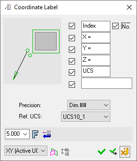
The dialog for the symbol is displayed.
|
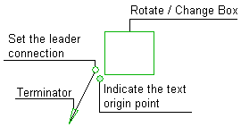
The image below shows an example of the symbol with each element labeled.
The dialog elements for this symbol are described below.
|
|
|
|
Annotate the symbol either in the dialog or in the graphics window (once the symbol has been positioned).
To edit (or to re-position) a symbol after it has been created:
Double-click the appropriate symbol. The relevant dialog associated with the symbol is displayed. This means that you are now in edit mode.
Edit the symbol elements and/or re-position the symbol as required.
Symbol Elements
|
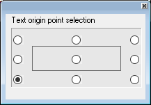
Indicate the Text Origin Point |
Define the origin point of the text box by selecting one of the points displayed around the text. The following dialog is displayed:
8 points are marked around the text box from which to define the origin point.
|
||||||
|
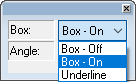
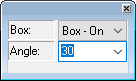
Rotate/Change Box |
Display the entity with/without a box or underline and orientate it at a specified angle.
|
||||||
|
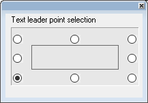
Set the Leader Connection |
Define the exit point of the leader by selecting one of the points displayed around the text.
|
||||||
|
Terminator |
Select the required terminator shape from the dropdown list. |
Dialog Buttons
|
Index Number |
When the checkbox is ON, display the Index value and/or the Index Number in the label. Edit the parameter value if required. The Index number (starting from 1) reflects the creation order of these PMIs. If such a PMI is deleted, the index of all PMIs in the file are updated. The "Index" text and the index number checkboxes can be selected independently of one another. |
|
X |
When the checkbox is ON, display the X parameter in the label. Edit the parameter value as required. |
|
Y |
When the checkbox is ON, display the Y parameter in the label. Edit the parameter value as required. |
|
Z |
When the checkbox is ON, display the Z parameter in the label. Edit the parameter value as required. |
|
UCS |
When the checkbox is ON, display the entered text adjacent to the UCS name in the symbol. |
|
<Comment> |
When the checkbox is ON |
|
Precision |
Set the level of precision from the dropdown list. This sets the number of places after the decimal point. |
|
Reference UCS |
All the values of the selected points are calculated using the location and orientation of the UCS selected from the dropdown list. |
|
|
Set the required font size in the text. Default = 5 |
|
|
Font: Select the font type in which to display the entity. The five most recently used fonts are displayed at the top of the list. |
|
|
Restore Default: Reset all values and settings to the system defaults. |
|
|
Active M-View: Change the projected plane to a preset orientation by selecting the appropriate M-View from the dropdown list. From this point onwards, the projection of this M-View is the default projection for all new entities. PMI M-Views can be added to this list as required. |
|
|
Define Plane: Change the projected plane by picking a planar face, plane, or 3 points to define the active plane. From this point onwards, the projection of this plane is the default projection for all new entities. A plane of any orientation may be defined. |
|
|
Selection Mode (Reference Entities): Pick reference entities (points, edges, etc.) from parts outside the active assembly or part. By default, if an assembly is activated, you can only pick reference entities from sub-assemblies or parts within the active assembly. Similarly, if a part is activated, you can only pick reference entities from the active part. The |
|
|
OK: Accept the changes, perform the operation, and close the current dialog/task. |
|
|
Apply: Accept the changes, perform the operation, and keep the current dialog/task open. |
|
|
Cancel: Cancel all changes and close the dialog/task without saving the settings. |


|