|
|
PMI: Graphical PMI & Hole Attributes
The PMI (Product Manufacturing Information) in CATIA, Creo, and NX files is imported into Cimatron as Graphical PMI, which is displayed exactly as it is shown in its original system. This ensures that all types of PMI are fully imported.
Important Note: Graphical PMI data is not associative to the imported model. It correctly represents the CATIA, Creo, and NX files only at the stage that the file was imported. Graphical PMI data can be viewed but not edited. It will not be updated after scale or move operations or when the body is changed.
In addition, Cimatron converts hole features from CATIA and NX files into special text that when clicked shows the complete data as defined in the original file format as shown below.
Graphical PMI
Cimatron supports Graphical PMI from CATIA, Creo, and NX files. PMI data in CATIA, Creo, and NX files is imported into Cimatron as Graphical PMI (displayed exactly as it is shown in its original system). Graphical PMI data is an entity that can be viewed but not edited.
To enable the display of Graphical PMI, select the DI PMI checkbox (under the Drafting Symbols (PMI) section) in the Selection Filter dialog.
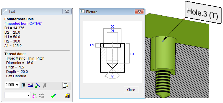
Hole Attributes
Cimatron supports Hole Attributes from CATIA and NX files. When importing a part or assembly from CATIA and NX files and a hole attribute exists in the original file, it is converted into a special text entity in the plane normal to the hole axis and with the label arrow pointing to the center point at the base of the hole (see the image above). In addition, a Set called DI Hole Attribute is created that stores all the imported PMI data.
The text entity (hole label) displays the string "Hole" and then the hole number given by the import mechanism. If the hole also includes threads, the letter "T" also appears in the string label.
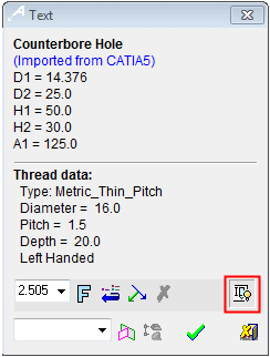
The PMI Text dialog that is displayed, in this case for the hole attributes, differs from the regular PMI Text dialog. In this case, the following Text dialog is displayed:
|
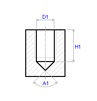
This Text dialog displays dimension data about the hole and additional data if threads are present. Data is only displayed for fields that are not empty. The lower buttons are similar to those in the regular PMI Text dialog. Pressing the Show Picture button (highlighted in red) displays an additional dialog showing a schematics of the hole type. See below for additional information on the hole types and parameters. |
||
|
|
|
|
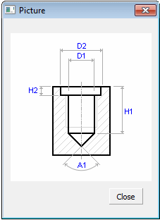
The following hole type schematics are displayed, depending on the hole type:
|
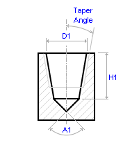
No Counter (Simple Hole) |
Tapered Hole |
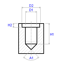
Counterbore Hole |
||||||||||||||
|
|
|
|
||||||||||||||
|
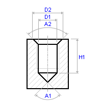
Countersunk Hole |
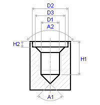
Counterdrilled Hole |
Dimensions displayed: |
||||||||||||||
|
|
|
|
In addition to the basic parameters, the following parameters are also displayed (if they exist):
The maximum and minimum tolerance parameters for the following:
- Primary diameter
- Counterbore diameter
- Countersink diameter
- Counterdrilled diameter
Thread data:
- Type
- Diameter
- Pitch
- Depth
- Max Tol.
- Min Tol.
- Right or Left Handed
|