|
|
Milling Orientation
Analyze the part, stock and cutter and suggest a best milling direction. This option appears in the Rough Parallel and Rough Spiral procedures.
The following Milling Orientation options are available, in a dropdown list:
|
As UCS |
The milling orientation is defined by the active UCS. |
||
|
Automatic |
Perform an analysis to find the best milling direction, taking into account the part, stock and cutter - the system automatically selects the direction. This analysis is performed at run time, during procedure execution, based on user-defined parameter settings. The Automatic mode in Rough procedures can be used for creating multiple Rough procedures that will rough the entire part from different directions. The following table parameters are displayed for the Automatic option:
These parameters are similar to those displayed for the Interactive option. See below for parameter explanations. Process Manager for Automatic mode: |
||
|
Interactive |
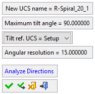
Perform an analysis to find the best milling direction, taking into account the part, stock and cutter - the user then selects one of the system-suggested milling directions. This analysis is performed while the procedure is open (before the procedure execution), based on user-defined parameter settings and enables you to manually select one of the system-suggested milling directions. The following table parameters are displayed for the Interactive option:
Clicking the Access button for Suggested Direction displays the following screen parameters:
See the example procedures below. Process Manager for Interactive mode: |
Parameters
|
Angular Resolution |
Specify the angular deviation to limit the number of directions analyzed. Using a smaller Angular Resolution increases calculation time, but may result in a better analysis result. |
||
|
Halt Rough Process on no Machining |
If the previous procedure is Rough, with identical parameters, that stopped calculation due to the Minimum Volume to Mill setting (see below), then do not calculate anything and create an empty toolpath. |
||
|
Maximum Tilt Angle |
The maximum tool tilt angle allowed when calculating the best milling direction. The tilt angle limit is calculated in relation to the NC Setup UCS Z axis, or the procedure UCS Z axis. This parameter enables you to limit the tool motions. |
||
|
Minimum Volume to Mill |
Skips toolpath calculation if the estimated volume to mill is less than the defined value. |
||
|
New UCS Name |
This parameter is displayed if Milling Direction = Interactive is selected. |
||
|
Tilt Ref. UCS |
Set the reference UCS to be used for tool tilting when calculating the best milling direction. The following options are available: |
||
|
Setup |
Start the calculation from the NC Setup UCS. The calculation is associative to changes of the UCS in the NC Setup. It is associative only if the reference UCS is set to Setup. It sets the "s" symbol, but does not suspend the motions. |
||
|
Procedure |
Start the calculation from the Procedure UCS. |
||
|
Analyze Directions |
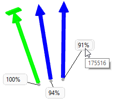
Start the suggested milling direction analysis, taking the above parameter settings into account. This calculates up to 3 milling directions and shows them as arrows in the graphics window. The system calculated direction that removes the most stock is initially displayed in GREEN (the green arrow also represents the active direction); the other directions are displayed in BLUE. Example of the GREEN arrow indicating the active direction:
Arrows that have a flat face at the tip, indicate that the direction is snapped to a planar floor and the faces are highlighted. These type of arrows are displayed as follows:
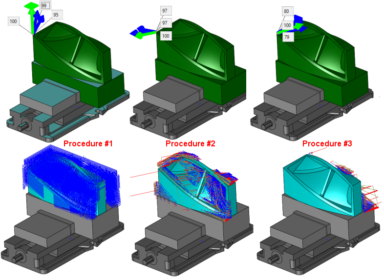
Switch directions by clicking on an appropriate arrow; clicking a blue arrow turns it green and the previous green arrow to blue. See the example procedures, below. Beside each arrow, a label displays a percentage number specifying the amount of removed stock. The best direction shows 100%. A tooltip on the label shows the approximated volume this direction can remove.
If Z-Top, Z-Bottom or other user boundaries are set, a confirmation message is displayed that these boundaries will be ignored during the analysis. Upon executing the procedure, the user-defined best milling direction is used. |
Buttons
The following buttons are in the dialog
|
|
OK: Accept the changes, perform the operation, and close the current dialog/task. A UCS is created on the selected suggested direction and is set as the procedure UCS. |
|
|
Apply: Accept the changes, perform the operation, and keep the current dialog/task open. A UCS is created on the selected suggested direction and is set as the procedure UCS. |
|
|
Cancel: Cancel all changes and close the dialog/task without saving the settings. |
|
|
Exit: Exit the operation and close the dialog/task. Parameter settings are saved. |
Examples
The example below shows three Rough Spiral procedures, using the Interactive mode. For each procedure, the preferred direction has been calculated (shown in the top row of images) and received the best results (shown in the bottom row of images).
This calculates up to 3 milling directions and shows them as arrows in the graphics window. The GREEN arrow represents the active direction; the other directions are displayed in BLUE. Switch directions by clicking on an appropriate arrow.


|


