|
|
Volume Milling  > Rough Spiral

Access:
-
For Technology, choose Volume Milling as the main selection, and Rough Spiral as the subselection.
Remove volume material. Cutting is performed in horizontal layers. The milling is performed in spiral motions.
For each layer, optimal machining strategy is applied according to the layer geometry. Priority is given to air plunging.
Adaptive feed control is available so a constant load is maintained on the cutter at all times. This option can be switched off.
High speed milling strategies can be applied.
You can create a few concurrent Rough procedures, for example, with different cutters, and the remaining material is taken into consideration.
See the ReRough Notes below.

ReRough Notes: The ReRough procedure was removed in Cimatron 11 as it was very similar to the Rough Spiral procedure. From Cimatron 11 onwards, when loading old ReRough procedures, they are automatically converted to Rough Spiral procedures. The conversion points detailed below apply:
-
The following parameters in Rough Spiral did not exist in ReRough and are initialized when converting:
-
Enable Nesting (Boundary Settings parameter table) = No.
-
Min. Stock Width (Stock parameter table) = 0.
-
-
All toolpath motions from the old ReRough procedure are kept in the Rough Spiral procedure.
-
A message is displayed in the Output Pane informing you that a "Volume Milling-ReRough" procedure was converted to a "Volume Milling-Rough Spiral" procedure.
See Creating a Procedure for a general explanation.
-
For Technology, choose Volume Milling as the main selection and Rough Spiral as the subselection.
-
Choose the appropriate cutter.
-
Define the part surfaces and, only if necessary, define the boundary area.
Notes:
-
-
If the boundary area is the same as the stock area, do not define a boundary area.
-
Define a boundary if the area to be milled meets one of the following criteria:
-
-
The boundary is completely within the stock area.
-
The boundary extends beyond the stock by a distance of, at least, the tool diameter.
-
-
-
-
Define the following Motion Parameters:
-
Define the machine parameters.
-
When finished, you can choose from the following Work Mode Dialog buttons:
(These options are also available on the Procedure popup submenu.)
Pre-Drilling Operations
The Pre-Drilling Operations feature automatically calculates the optimal locations for pre-drilling holes in the stock that will be used by the roughing operation for plunging. Cimatron identifies these plunging points and creates the necessary drilling operations where required, esentially transforming a procedure into a multi cutter procedure.
Pre-Drilling Operations works with the following Volume Milling procedures and also supports Micro Milling.
General Interaction
-
After you have created a procedure and selected a technology (see step 1 in Creating this procedure above), go to the Parameter table and select Motion Parameters > Entry & End Points.
-
From the Pre-Drilling Operations parameter, select By Cycle from the dropdown list.
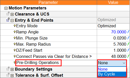
Note that two additional parameters are now displayed, Define Cycle and Drill Holes First.
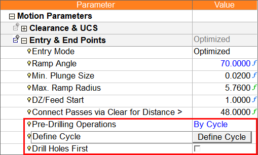
-
Click the Define Cycle button to open the Define Cycles dialog.
-
From the Define Cycles dialog, select and enter the appropriate criteria to define a drilling cycle(s). See Define Cycle for more information.
-
Select the Drill Holes First checkbox as required.
-
Define the machine parameters.
-
When finished, you can choose from the following Work Mode Dialog buttons:
(These options are also available on the Procedure popup submenu.)
|