|
|
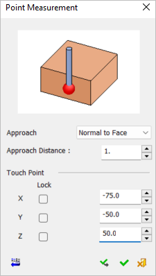
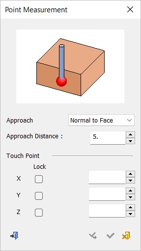
Measurement Cycle: IPM Point
Measure the coordinates of a point.
The Point Measurement dialog is displayed below. Select a point to automatically enter its coordinates or enter the coordinates manually.
Note: When indicating measurement cycles by point for OMI, you can select multiple points by box with each selected point creating a point cycle. See On Machine Inspection (OMI) Multiple Point Selection below.
|
Cycle Selection > |
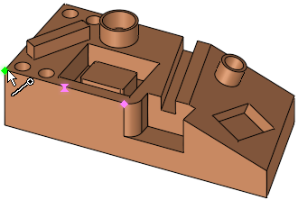
When a location is selected (based on the default options in the Selection Filter), a probe is displayed at the defined measurement point(s). |
|
|
|
|
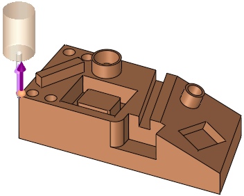
In this cycle, the approach direction is set to normal to the picked face, but it can be changed to be along the X, Y, Z main direction or to a user-defined direction using the direction arrow. |
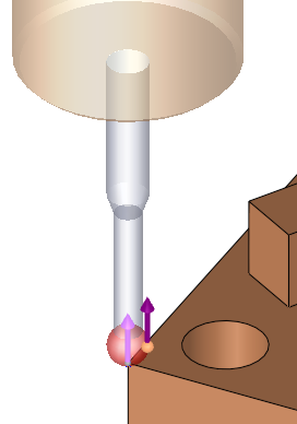
The probe is displayed. A PINK arrow is shown on the picked point showing the opposite direction to the probe approach motion (which is the direction the probe will advance towards the geometry while measuring). |
|
|
|
See:
Cycle selection parameters
Lock options
Measurement Cycle dialog buttons
Cycle selection parameters
|
Approach Direction |
This is a dropdown list to set the direction the probe will advance towards the geometry while measuring. The following options are available: Normal to Face (default) A PINK arrow is shown on the picked point showing the opposite direction to the probe approach motion. In example above, the approach direction is set to normal to the picked face. |
||
|
Approach Distance |
The size of the measuring motion, which determines how far the probe will be positioned away from the measured point. |
||
|
Touch Point |
The combination of the above parameters defines the measurement values of the following parameters:
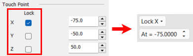
These coordinates may be entered manually or edited manually after the entity selection. In either case, the position of the probe is also updated. Coordinate Lock options This option allows you to lock the Touch Point X, Y, or Z coordinates from the Point Measurement dialog. When ON (selected), the screen parameters in the Graphic Pane automatically display the Lock X, Lock Y, or Lock Z option along with its corresponding value. In addition, a BLUE plane appears. The At = screen parameter enables you to move the plane to the required position; selection will only be available on that plane. If the value of the coordinate is changed, the screen parameter and blue plane will change accordingly.
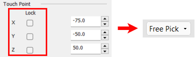
When OFF (unselected), the screen parameter defaults to the Free Pick option and the coordinate values do not change. |
Lock options
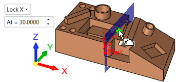
Screen parameters are displayed to specify the lock options to display a plane on the selected lock axis and limit selection to that plane only.
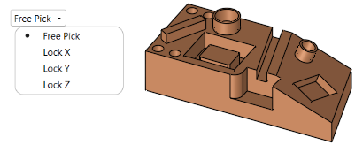
When a lock option is selected (not free), an adjacent parameter value enables you to move the plane to the required position (selection will only be available on that plane).
|
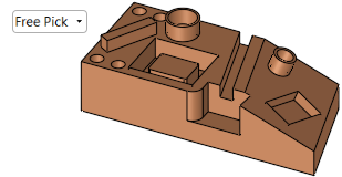
Free Pick enables selection with no plane limits |
Selection is only available on the Lock X plane |
|
|
|
|
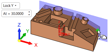
Selection is only available on the Lock Y plane |
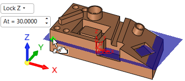
Selection is only available on the Lock Z plane |
|
|
|
Measurement Cycle dialog buttons
The following buttons appear in the measurement dialog.
|
Exit: Exit the operation and close the dialog/task. |
|
|
Reset: Reset all values and settings to the system defaults. |
|
|
|
Apply: Accept the changes, perform the operation, and keep the current dialog/task open. This button appears only when invoking the measurement cycle from the On Machine Inspection procedure. |
|
OK: Accept the changes, perform the operation, and close the current dialog/task. |
|
|
Cancel: Cancel all changes and close the dialog/task without saving the settings. |
On Machine Inspection (OMI) Multiple Point Selection
When indicating measurement cycles by Point for OMI, you can select multiple points by box with each selected point creating a point cycle.
Note: All points in a single box selection are ordered by the closest point by default (Optimized Sort), starting from the bottom-left corner of the bounding box of all selected points; however, there are multiple options for determining the point order (see item 3 below).
From the Measurement Cycles dialog, select Point as the measurement type.
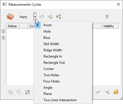
The Point Measurement dialog appears.
The following parameters also appear in the Graphics pane (graphics display area). Set the parameter options as needed and proceed to select the points by box.

|
Optimized Sort |
Toggle parameter to determine measurement order. The options are:
|
||||||||
|
Free Pick |
Toggle parameter that specifies the lock options to display a plane on the selected lock axis and limit point selection to that plane only.
|
When all parameters/options have been defined, click Apply ![]() to apply your selections or OK
to apply your selections or OK ![]() to apply your selections and exit the Point Measurement dialog.
to apply your selections and exit the Point Measurement dialog.
|