Measurement Cycle: On Machine Inspection

Access: Open this function from one of the following locations:
-
Select the value field in the Measurement Cycle parameter of the Motion Parameters table branch.
Select the required cycle from the dropdown list in the Measurements Cycles dialog. -
Select the value field in the Cycle Data parameter of the Geometry Parameters table branch.
Select the required cycle from the dropdown list in the Measurements Cycles dialog.
Enable the programming of multiple probing measurements at the end of machining while the part is still on the CNC machine, automatically generating a Quality Assurance (QA) report.
Dialog
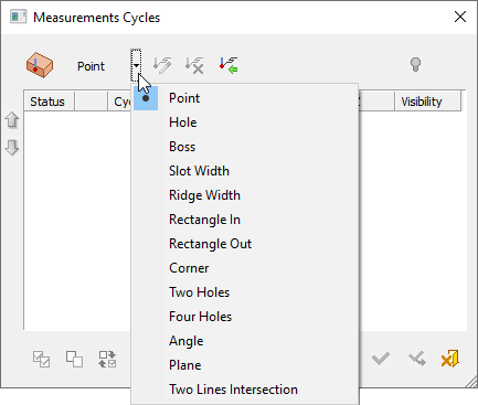
The Measurements Cycles dialog is displayed. All available measurement cycles are shown in a dropdown list. These are the same cycles that are available in the In-Process Measurement Dialog. Some machines support more cycle types while others do not support all the ones this procedure offers. Included are the cycle types that are the most commonly used. InvokeInvoke the required measurement cycle to display the relevant cycle dialog.
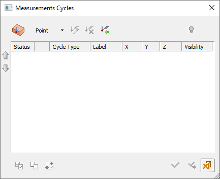
|
Initial empty dialog |
Click the Arrow button to display a dropdown list of all the available measurement cycles |
|
|
|
Setting measurement cycles
To indicate measurement cycles (positions that require measurement), either select the required cycle from the dropdown list (which also appears in the In-Process Measurement Dialog) or click the button to the left of the list.
The button always displays the last invoked measurement cycle (in the example above, it is the Point measurement cycle ![]() ).
).
Selecting a measurement cycle from the dropdown list (or button) displays the relevant measurement cycle dialog to indicate positions that require measurement.
Select a cycle to invoke its dialog and set the parameters.
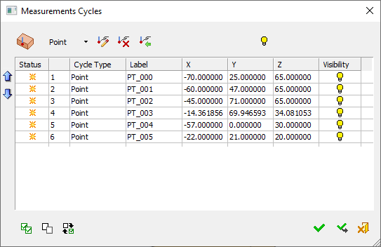
|
Dialog with multiple measurement cycles |
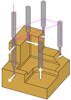
Multiple probe figures and arrows displayed on the screen |
|
|
|
Options
|
Status |
The |
|
Serial # |
Serial number |
|
Cycle Type |
Displays the measurement cycle type |
|
Label |
The label number as displayed in the Import Measurement Results |
|
X, Y, Z |
XYZ coordinates of the touch point of the measurement probe |
|
Visibility |
Hide or show the relevant probes on the geometry screen. |
Using Apply to add multiple measurement cycles
Since multiple cycles can be added to this procedure, when cycles are invoked from the Measurements Cycles dialog, the Apply ![]() button is added to the bottom of the dialog that enables you to define a cycle, apply it, and remain in the dialog to define additional cycles of the same type.
button is added to the bottom of the dialog that enables you to define a cycle, apply it, and remain in the dialog to define additional cycles of the same type.
Hiding/showing probes
As more cycles are added, the display may get crowded with probe figure and arrows. The  button on each row hides/shows the relevant probe. The button at the top of the dialog hides/shows the probes for all selected cycles.
Managing measurement cycles in the dialog
Moving – Use the 
 arrows to move selected cycles up or down to reorder the list.
New items – The  symbol in the Status column indicates that this row contains a new item and that it has yet to be approved. This sign is removed when you click OK or Apply.
Editing, deleting, importing – Cycles can be edited ![]() , deleted
, deleted ![]() , or imported from a CMM file
, or imported from a CMM file ![]() .
.
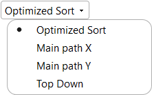
Setting a measurement order (for Point Measurement only)
When setting a measurement order for points, a screen parameter enables you to specify the order of point measurement. The following options are available:
|
|
|
See also: On Machine Inspection - Multiple Point Selection
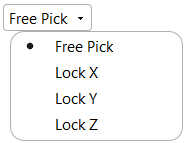
Selecting a measurement position
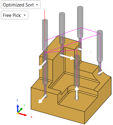
When selecting a measurement position, a screen parameter enables you to either select measurement locations in all planes or lock a selection to a specific plane. The following options are available:
|
|
|
|
Free Pick on all planes |
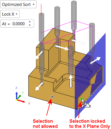
Lock X to limit selection to the X plane and set a plane offset |
|
|
|
Dialog Lock options
Lock options can also be selected from the various measurement cycle dialogs (the Point Measurement dialog below is used as an example).
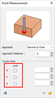
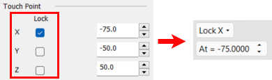
When the Lock checkbox is ON (selected), the following occurs:
-
The screen parameters in the Graphic Pane automatically display the appropriate Lock option along with its corresponding value (see images below).
-
A BLUE plane appears. The At = screen parameter enables you to move the plane to the required position; selection will only be available on that plane.
-
If the value of the coordinate is changed, the screen parameter and blue plane will change accordingly.
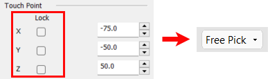
When the Lock checkbox is OFF (unselected), the following occurs:
-
The screen parameter defaults to the Free Pick option and the coordinate values do not change.
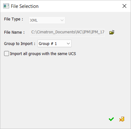
Import Cycle from CMM File
Predefined cycles can be imported from a CMM (Coordinate Measuring Machine) file.
-
Select
 to display the File Selection dialog.
 -
Browse to and select the relevant XML file.
-
Select Group to Import to define the group of cycles to import from the CMM file and whether to import all groups with the same UCS.
Dialog buttons
The following buttons are in the dialog
|
|
Select Cycle: Invoke the cycle dialog of the measurement cycle displayed in this button. The last invoked measurement cycle is always displayed. To the right of this button, the arrow button displays a dropdown list of all the available measurement cycles (which also appear in the In-Process Measurement Dialog). Select a cycle to invoke its dialog and set the parameters. |
|
|
Edit Cycle: Edit the selected cycle. Display the relevant measurement cycle dialog. |
|
|
Delete Cycles: Delete the selected cycles. |
|
|
Import Cycles from CMM file: Import predefined cycles from a CMM (Coordinate Measuring Machine) file. |
|
|
Hide/Show: Toggle button to hide or show a probe. As more cycles are added, the display may get crowded with probe figure and arrows. The Hide/Show button on each row hides/shows the relevant probe. The Hide/Show button at the top of the dialog hides/shows the probes for all selected cycles. |
|
|
Move: Move selected cycles up or down to reorder the list. |
|
|
Select All: Select all items. |
|
|
Unselect All: Unselect all items. |
|
|
Toggle Selection: Toggle the selection of all items. Items that are selected become unselected, and vice versa. |
|
|
OK: Accept the changes, perform the operation, and close the current dialog/task. |
|
|
Apply: Accept the changes, perform the operation, and keep the current dialog/task open. |
|
|
Cancel: Cancel all changes and close the dialog/task without saving the settings. |
