|
|
Sharp Edges Parameters
The use of these parameters enables selected edges to remain sharp after machining. This is accomplished by preventing the cutter from rolling over the selected edges, as in some cases, this might damage the sharpness of the edge.
These parameters are available in the Tool Trajectory parameter branch in the procedures Surface Milling > Finish Mill All (when the Machining Method is set to Layers or Helical) and Surface Milling > Finish By Limit Angle. These parameters are only displayed after you have defined the edges that are to remain as sharp edges.
To keep selected edges sharp after machining:
Make sure that the Part Surface Offset (under Tolerance & Surf. Offset parameter branch) is set to 0. If there is a positive surface offset, the system no longer considers the edges as sharp.
Pick the edges that are to remain as sharp edges.
When these edges are selected, the parameters below are displayed in the location mentioned above.
Set the parameters as required.
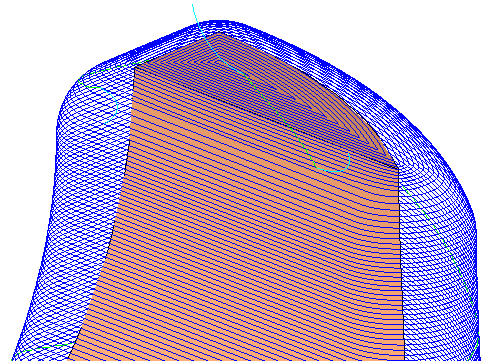
In this case, the cutter rolls over the sharp edges. This includes the constant Z motions that roll over the vertical edges, and the spiral milling at the top of the electrode that rolls over the horizontal sharp edges, as well as over the sharp corners. Milling in this way might cause the sharp edges to become not so sharp.
Once the sharp edges have been selected, the following parameters are displayed:
|
Sharp Edge Passes Connections |
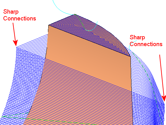
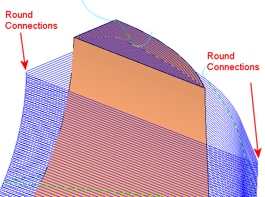
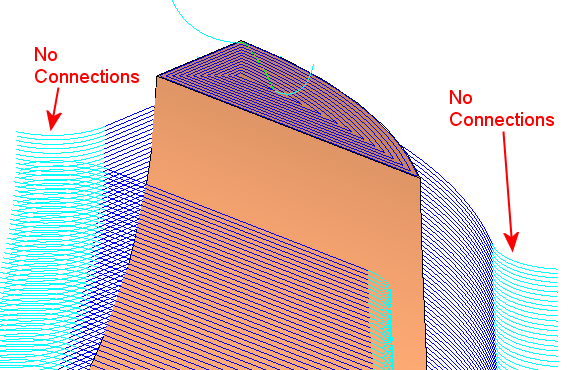
Sharp edge passes (short) connections are those that are typically created by a vertical sharp edge. This parameter enables you to create different types of connections for toolpath motions, where the cutter touches sharp edges over the short connections. The following options are available from the dropdown list:
In the examples given above, for each of these options, the spiral milling at the top was restricted to the horizontal area and the waterfall (see the note below) over the sharp horizontal edges was prevented. Also, some of the constant Z motions were completely removed because they touched the horizontal edges at the top. This may or may not be desirable - see the explanation for the Mill Waterfalls in Vertical Regions parameter below. |
||||||
|
Mill Waterfalls in Vertical Regions |
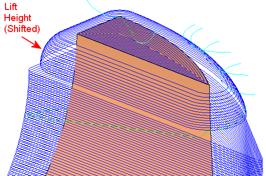
These (long) connections are those that are typically created by horizontal edges. This parameter, if selected, enables you to raise toolpath motions so that they do not touch the sharp edges over the long connections. Note: The waterfall effect happens when the tool rolls over a sharp corner at the outer edge of a part, and falls behind it. This usually results in the rolling tool chopping off the edge, especially at high feed rates. If the checkbox is selected, the following parameter is displayed:
Usage Note: In the examples given above, when setting the short connection type, the region above the constant Z layers is not machined because it is part of the waterfall over the horizontal sharp edges at the top. If the stock left for this Finish operation is very thin, there is no problem for the cutter to remove it. However, if the stock is thicker, the first layer will have to remove too much material. This can be avoided by creating the original waterfall motions and lifting them by a specified amount, so that they do not touch the sharp edges. |
|
