|
|
Part Surface Offset
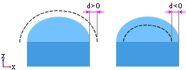
The global offset from the Part Surface (or part2 surface) at which milling will be performed.
(This parameter is set in the Tolerance & Surface Offset section of the Procedure Parameter Table.)
Notes:
-
The Advanced option of the Tolerance & Surface Offset table enables you to define different Wall and Floor offsets for Part Surfaces and Check Surfaces.
-
If more than 1 Part and/or Check Surface Groups are defined (in the Geometry Parameters Table), the Advanced Tolerance & Surface Offset table may appear as followsas follows:
In this example, 3 part surface groups and 2 check surface groups are defined in the Geometry Parameters Table.
In the Advanced Tolerance and Surface Offset table, this allows you to define different Wall and Floor offsets for each group of surfaces.
-
A negative part offset value (the absolute value) must be <= the cutter's corner radius.
Part Surface Offset examples
The procedure for setting Single and Multiple Offsets is identical for Check and Part Surfaces.
Single Offset
|
When 1 Part and/or Check Surface Group is defined in the Geometry Parameters Table, the Tolerance and Surface Offset table enables you to define a single surface offset for the whole group (in the Advanced option, different Wall and Floor offsets can be defined for the group as a whole). |
The single offset may look like this: |
The single offset encompasses all the part/check surfaces. |
|
|
|
|
Multiple Offsets
|
When more than 1 Part and/or Check Surface Group is defined in the Geometry Parameters Table, the Tolerance and Surface Offset table enables you to define different surface offsets for each group (in the Advanced option, different Wall and Floor offsets can be defined for each group). |
The multiple offsets may look like this: |
|
|
|
|
Each group of part/check surfaces can have a different offset. |
||
|
|
|
|
|