Frame Settings 

Access: Open this function from one of the following locations:
-
Select Sheets > Settings > Frame Settings from the menu bar.
-
Select Frame Settings on the popup menu in the Drawing Tree (right-click the Frame
 in the Drawing Tree).
-
Double-click the Frame
in the Drawing Tree.
A customized frameframe can be created for each sheet in the drawing. This frame contains a title block with engineering informationengineering information.
A Preference setting enables you to select and include a default frame for every drawing sheet.
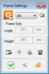
The Frame Settings dialog is displayed:
|
|
Buttons:
|

In this topic
- Add an Existing Frame (existing in Cimatron)
- Add an Existing Frame from Another CAD/CAM System
- Add a New Frame
- Edit Cimatron Frames
- Edit Text in Cimatron Frames
- Delete Text in Cimatron Frames
- Move Cimatron Frames
- Insert Entities into the Frame
- Convert Cimatron IT Frames to Cimatron Frames
Adding an Existing Frame (existing in Cimatron)
- InvokeInvoke the Frame Settings function. The Frame Settings dialog is displayed.
-
To select a frame that is not in the default Frames folder, press the Browse button
 and browse to the required folder.
The default Frame settings are stored in FRM files in the following folder:
...\Program Files\Cimatron\Cimatron\2026.0\SourceData\frames\
-
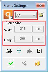
Click the frame dropdown list and select the specific frame from the dropdown menu. The frame is previewed in the graphic area. The dimensions of the frames are listed in the Width and Height boxes and cannot be modified.
Examples:
The frame dropdown list is selected as A4 and the frame size is displayed in the Width / Height boxes.
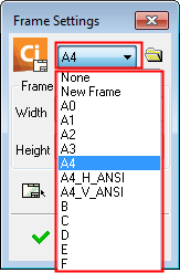
Selecting a frame type from the dropdown list.
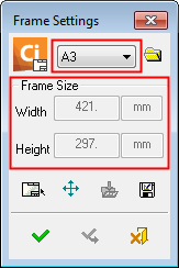
An A3 frame type is selected and the frame size is displayed below it.
- Click the OK
 button
  to apply the Frame to the drawing.
Add an Existing Frame from Another CAD/CAM System
-
To add entities from the view to a Cimatron frame, create a group out of the entities, and then explode the group instance into a new sheet.
-
Create the frame from that sheet by adding a new frame and then inserting entities from the sheet into the frame.
Add a New Frame
-
InvokeInvoke the Frame Settings function. The Frame Settings dialog is displayed.
-
Click the frame dropdown list and select New Frame from the dropdown menu.
-
Click Edit Frame
 button in the Frame Settings dialog and enter the Sketcher environment.
 -
Draw a frame, exit the sketcher and click Apply in the Frame Settings dialog.
-
Click Apply/Close
to apply the new Frame to the drawing.
Edit Cimatron Frames
-
InvokeInvoke the Frame Settings function and click Edit Frame
in the Frame Settings dialog, or right-click the Frame item in the Drawing Tree and select Edit Frame. -
Double-click on an area of the frame to enter edit mode. In this mode you can create a sketch, hatch or edit text. Modify the frame as you would an ordinary sketch.
-
Exit the sketcher and click Apply
 to save the change.
Edit Text in Cimatron Frames
-
Double-click the text (within the frame) to be edited. The Text editing dialog is displayed.
-
Edit the text as required.
-
Click Apply
to save the changes.
Delete Text in Cimatron Frames
-
Pick the text (within the frame) to be deleted. Multiple texts can be selected using Pick By Box.
-
Perform the Delete operation. A deletion confirmation message is displayed requiring a Yes/No/Cancel response.
-
Yes: Delete the selected items.
-
No: Delete the selected items but not the frame text.
-
Cancel: Cancel the delete operation.
-
Move Cimatron Frame
-
InvokeInvoke the Frame Settings function and click Move Frame
 in the Frame Settings dialog, or right-click the Frame item in the Drawing Tree and select Move Frame.
 -
Drag the frame to any area on the screen. A toggle option is displayed Move Frame Content / Don’t Move Frame Content , enabling you to choose whether or not to drag the frame contents when dragging the frame.
-
Click Apply
to save the changes.
Insert Entities into the Frame
-
InvokeInvoke the Frame Settings function and click Edit Frame
in the Frame Settings dialog, or right-click the Frame item in the Drawing Tree and select Edit Frame. -
Click Insert entities from sheet
 and pick the sheet items (text, sketch, hatch, embedded pictures) to be incorporated in the frame.
 -
Click Apply
to add the entity and Apply/Close to exit the Frame function.
Convert Cimatron IT Frames to Cimatron Frames
-
Import the Cimatron IT (.pfm) file. (Click the Parameters tab, and under Module select the Drafting option).
-
Expand the Sheet 1 feature and double-click the Frame button
; the frame is displayed in the graphic area together with the Frame Settings dialog. -
Select New Frame in the dropdown list.
-
Click Edit then Insert entities from sheet
to insert all the displayed entities into the frame. -
Click Apply
then Save the frame under a new name.The frame is now a standard Cimatron frame and is added to the dropdown list. It can be opened and edited in any drawing.