Machine Definition 

Access: Open this function from one of the following locations:
-
Select NC Utilities > Utilities > Machine Definition from the menu bar.
-
Cimatron Control Panel: Select Start > All Programs > Cimatron > Cimatron Control Panel.
Select NC > Machine Definition.
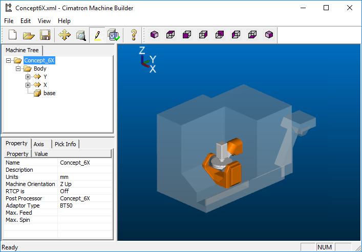
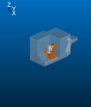
This application enables you to construct a machine definition for the Machine Simulator. It enables defining the kinematics tree structure, the axes, and the displayed components of the CNC machine. This enables you to simulate the G-Code motions on a virtual machine that imitates the real machine behavior.
Important! This application is for use by qualified personnel only. Contact your Cimatron Provider or Reseller to get a machine definition for the Machine Simulator.
For Turning procedures: Configure the turning (lathe) machine parameters and create the saved file as a Machine Definition Document (MDD) file. The MDD is a prerequisite for enabling turning operations.
The Machine Builder dialog is displayed.
|
|
The Machine Definition library of machine models are stored in XML files in the following folder:
...\ProgramData\Cimatron\Cimatron\2026.0\Data\Nc\MachineWorks
When saving a machine definition (new, edited, or imported), each definition is saved in a folder that contains all the relevant data (XML and STL files). The folder name and the name of the XML file are identical to the machine name.
Menu Bar
The Menu bar contains the following items; click a link to go to that section.
File Menu
|
New |
Create a new machine definition. |
|
Open |
Open a previously saved machine definition. |
|
Save Save a machine definition in one of the following Cimatron formats: |
|
|
Save As |
Save a machine definition in one of the following Cimatron formats:
|
|
Import |
Import ModuleWorks machine definitions. This operation imports a ModuleWorks XML file and assigns default values to any Cimatron-specific parameters so that it can be saved as a Cimatron format XML file. |
|
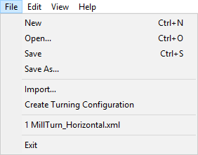
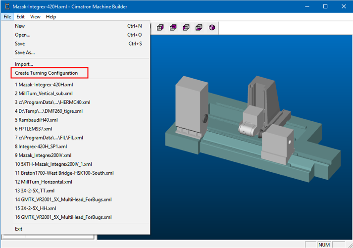
Create Turning Configuration |
Configure the turning (lathe) machine parameters and create the saved file as a Machine Definition Document (MDD) file. The MDD is a prerequisite for enabling turning operations. See Create Turning Configuration below. |
|
Recent File |
Displays a list of recently opened files Select a file to open it. |
|
Exit |
Exit the application. |
The options Open, Save, and Save As are used for operations on Cimatron format XML machine definitions.
Create Turning Configuration
Configure the turning (lathe) machine parameters and create the saved file as a Machine Definition Document (MDD) file. This option depends on the settings of the Machine Builder dialog attributes Turning Enable and Sub-Position.
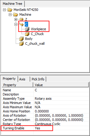
- If the parameter Turning Enable = YES in the Machine Builder dialog, the File > Create Turning Configuration option displays the Create Turning Configuration dialog .
- If no Rotary Axis has the property Turning Enable = YES, then the machine cannot be defined as a lathe, so a message is displayed and the Create Turning Configuration dialog is not displayed.
|
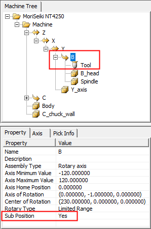
A rotary axis that has a workpiece located directly on it has the attribute:
|
A rotary axis that has a tool component directly under it has the attribute:
|
||
|
|
|
|
|
|
This defines as the milling axis |
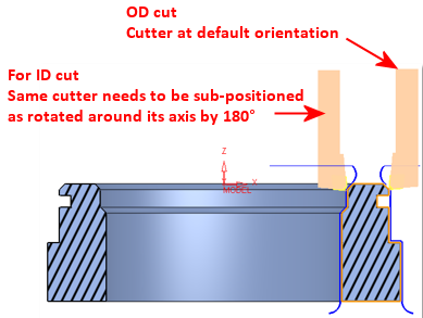
This results in a cutter orientation |
||
|
The File > Create Turning Configuration option displays the Create Turning Configuration dialog already configured: |
|
|
|
|
|
The file is saved as a Machine Definition Document (MDD) file.
The MDD files are saved in the same folder that contains the machine
definition XML file. The system retains the relation between a machine
and its MDDs by keeping them in the same folder. MDD files may either
be system supplied or user-defined.
The Machine Definition library of machine models are stored in XML files in the following folder:
...\ProgramData\Cimatron\Cimatron\2026.0\Data\Nc\MachineWorks |
|
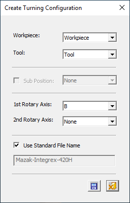 |
Workpiece |
Select the workpiece from the dropdown list which only lists items in the machine that are defined as "workpiece" and located on a rotary axis that has Turning Enable = YES only. Having Workpiece is mandatory. Note: Currently, only single spindle machines are supported and only one such axis is available. |
|
Tool |
Select one of the existing "Tool" elements of the machine. |
|
|
Sub-Position |
The sub position is related to the selected tool. |
|
|
Rotary Axes |
Cimatron supports 2 rotary axes. If more exist, only 2 can be active. If the machine is head-head or table-table, the axis order must be according to the tree definition. The axis is displayed in the dialog accordingly. Axes that are marked as "Spindle" or as "Sub Position" are not allowed to be "Rotary Axis" |
|
|
Use Standard File Name |
For the output file name, use a system default name or a user-defined name. When this checkbox is ON |

The following buttons are in the dialog
|
|
Save & Close: Save the settings and close the dialog. The file is saved as a Machine Definition Document (MDD) file. The MDD is a prerequisite for enabling turning operations. The MDD files are saved in the same folder that contains the machine
definition XML file. The system retains the relation between a machine
and its MDDs by keeping them in the same folder. MDD files may either
be system supplied or user-defined.
The Machine Definition library of machine models are stored in XML files in the following folder:
...\ProgramData\Cimatron\Cimatron\2026.0\Data\Nc\MachineWorks |
|
|
Cancel: Cancel all changes and close the dialog/task without saving the settings. |
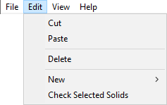
Edit Menu
|
Cut |
Cut a selected entity. |
|
Paste |
Paste a previously cut entity. |
|
Delete |
Delete a selected entity. |
|
New |
Create either a new assembly or a new mesh solid. Assembly: Displays a dialog enabling you to create an assembly 'under' the right-clicked item.
Mesh Solid: Displays the Open dialog enabling you to select a relevant mesh solid file to add 'under' the right-clicked item. |
|
Check Selected Solids |
Activate a number of checks on the STL files used to define the machine solids, and then produce a TXT file with the results. The following checks are performed:
Checks 1-4 are performed on each selected STL separately. Checks 5-6 are performed on each selected STL against all the STLs of that machine. Selected solids are those marked as selected or in attention; if the attention is on a branch of the machine tree, all the solids inside it are regarded as selected. |
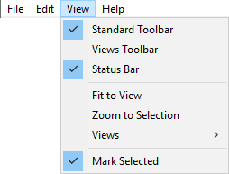
View Menu
|
Standard Toolbar |
Display the Standard toolbar - see below.
|
||||
|
Views Toolbar |
Display the Views toolbar - see below.
|
||||
|
Status Toolbar |
Display the Status toolbar.
|
||||
|
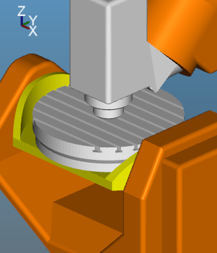
Fit to View |
The model/object in the display is automatically enlarged to the size of the graphics area window - see the note below regarding item selection.
|
||||
|
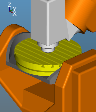
Zoom to Selection |
The selected component (colored yellow in the display area) is enlarged to the size of the graphics area window.
|
||||
|
Views |
Select the required view from a dropdown list. These are the same views as graphically displayed in the Views toolbar - see above. The following views are available - see Views for an explanation of most of these views:
|
||||
|
Mark Selected |
Highlight the selected area of the display for clarity - see the note below regarding item selection.
|

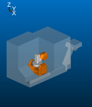
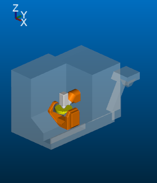
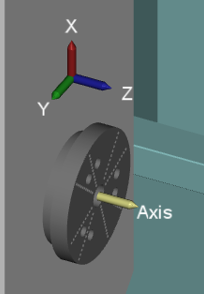
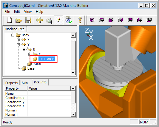
Note: To select an item in the display, select it from the Machine Tree.
ExampleExample
|
An item of interest selected in the Machine Tree is also 'selected' in the display area: |
|
|
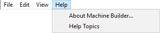
Help Menu
|
About Machine Builder |
Data about the application: name, version, etc. |
|
Help Topics |
Link to the Online Help. |
Toolbar
The following toolbars are displayed by default:
Standard Toolbar

These options are also available from the Menu Bar - see the relevant explanations.
|
|
New: Create a new machine definition. This command also appears in the File Menu explanation above. |
|
|
Open: Open a previously saved machine definition. This command also appears in the File Menu explanation above. |
|
|
Save: Save a machine definition in a Cimatron formats. See the File Menu explanation above. |
|
|
Fit to View: The model/object in the display is automatically enlarged to the size of the graphics area window. See the View Menu explanation above. |
|
|
Zoom to Selection: The selected component (colored yellow in the display area) is enlarged to the size of the graphics area window. See the View Menu explanation above. |
|
|
Mark Selected Items: Highlight the selected area of the display for clarity. See the View Menu explanation above. |
|
|
Check Selected Solids: Activate a number of checks on the STL files used to define the machine solids and then produce a TXT file with the results. See the Edit Menu explanation above. |
|
|
Help Topics: See the Help Menu explanation above. |


Views Toolbar
These options are also available from the Menu Bar - see the relevant explanations.
|
|
Isometric view |
|
|
Top view |
|
|
Front view |
|
|
Right view. |
|
|
Back view |
|
|
Left view |
|
|
Bottom view |
|
|
Isometric and Rotate |