Machine Definition  : Operations

Access: Open this function from one of the following locations:
-
Select NC Utilities > Utilities > Machine Definition from the menu bar.
-
Cimatron Control Panel: Select Start > All Programs > Cimatron > Cimatron Control Panel.
Select NC > Machine Definition.
This application enables you to construct a machine definition for the Machine Simulator. It enables defining the kinematics tree structure, the axes, and the displayed components of the CNC machine. This enables you to simulate the G-Code motions on a virtual machine that imitates the real machine behavior.
Important! This application is for use by qualified personnel only. Contact your Cimatron Provider or Reseller to get a machine definition for the Machine Simulator.
The Machine Builder dialog is displayed.
Machine tree
The Machine Tree, together with the tabbed tables below it, contain the kinematics tree structure representing a CNC machine. A number of operations can be performed in the Machine Tree by right-clicking on an item in the tree to display a popup menu.
|
Right-click an item |
Popup menu displayed |
|
|
|
The following operations can be performed on items 'under' the entity that is right-clicked:
|
Show |
Display the relevant items. See the examples below. |
|
Hide |
Hide the relevant items. See the examples below. |
|
Highlight |
Highlighted the relevant items. See the examples below. |
|
Select Contained Solids |
Select the contained solids of the relevant items (if the attention is on a branch of the machine tree, all the solids inside it are regarded as selected). These items are marked as selected in the Machine Tree and (if the option Mark as Selected is ON) also in the display. See the examples below. |
|
Select Adjacent Solids |
Select the adjacent solids of the relevant items. These items are marked as selected in the Machine Tree and (if the option Mark as Selected is ON) also in the display. See the examples below. |
|
Check Selected Solids |
Activate a number of checks on the STL files used to define the machine solids, and then produce a TXT file with the results. See the Edit Menu explanation above. |
|
Cut |
Cut the relevant items. |
|
Paste |
Paste the relevant items. |
|
Delete |
Delete the relevant items. |
|
New |
Create either a new assembly or a new mesh solid. See the Edit Menu explanation above. |
|
Properties |
Display the Property tab of the selected item. |
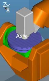
In the tree above, the selected item (B) contains the Work Piece, Round Table, and Tilt Table. In the examples below, the round table and tilt table are colored purple and green respectively for clarity.
ExamplesExamples
|
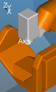
Show: The relevant items are displayed. |
Hide: The relevant items are hidden. |
Highlight: The relevant items are highlighted. |
|
|
|
|
|
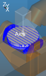
Select Contained Solids: The solids under the right-clicked entity are displayed in 'selected' mode: |
Select Adjacent Solids: The adjacent solids are displayed in 'selected' mode: |
|
|
|
|
|
|
Select Contained Solids: Items marked as selected in the tree. |
Select Adjacent Solids: Items marked as selected in the tree. |
|
|
|
|
Tabbed tables
The following tabs are displayed below the Machine Tree. The contents of each tab displays the properties of the item selected in the Machine Tree.
|
Property tab |
Axis tab |
|
|
|
|
|
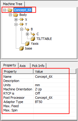
Property tab
The Property tab displays the properties of the item selected in the Machine Tree.
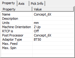
These properties change depending on the item selected in the Machine Tree, for example:
|
Main machine selected |
Tilt Table item selected |
|
|
|
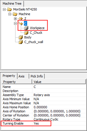
For a turning (lathe) machine, relevant parameters are displayed.
|
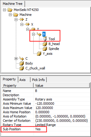
A rotary axis that has a workpiece located directly on it has the attribute:
|
A rotary axis that has a tool component directly under it has the attribute:
|
||
|
|
|
|
|
|
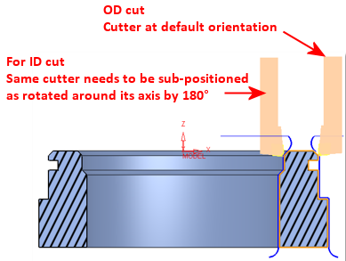
This defines as the milling axis |
This results in a cutter orientation |
||
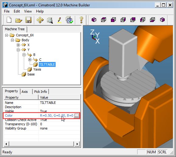
To edit a property, double-click its value. The property name is highlighted; edit the value as required. The results are displayed in the Machine Tree and or the display.
ExampleExample
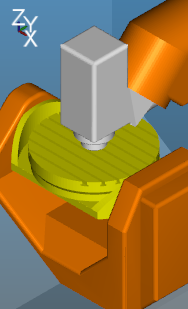
In this example, the color of the Tilt Table item is changed. Select the Color row in the Properties Tab and then select the required color from the color table.
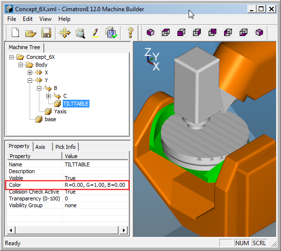
The new color of the selected item is displayed in the tab table and the display.
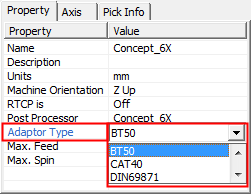
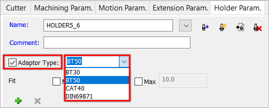
The Adaptor Type can be selected from a dropdown list. This parameter can be set in the NC Setup, Machine Definition, and also in the Holder Parameters tab of the Cutters & Holders dialog. This list of adaptors is the same for both locations and is saved in the following folder:
...\ProgramData\Cimatron\Cimatron\2025.0\Data\Nc\Machines-Adaptors.CSV
A warning is issued if the adaptor type of a holder is not identical to the adaptor type of a machine defined in the NC-Setup. The adaptor settings are compared and a warning is issued (if required) when the following occurs:
-
The holder specifies an adaptor.
-
The NC-Setup defines a Machine.
-
The Machine defines an adaptor.
-
The Adaptor type of the holder is different than the adaptor type of the machine.
If a warning message is displayed, you can either ignore and continue or cancel the selection of the holder. In the latter case, either modify the adaptor for the selected holder or select another holder with a suitable adaptor. When selecting a holder from the Holder Library, you can filter the holders by their adaptor type.
|
Adaptor Type Setting in |
Adaptor Type Setting in Cutters and Holder Dialog |
|
|
|
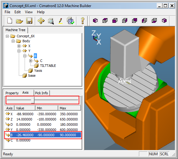
Axis Tab
The Axis tab displays the current axis value and also the minimum and maximum ranges for each axis of the item selected in the Machine tree. When selecting an axis in the Axis tree, the relevant axis is highlighted in the Machine Tree and in the display.
|
The X axis is selected |
Right-click to display the popup menu |
Home Position: Move the selected item to the home position of the axis. Zero Position: Move the selected item to the zero position of the axis. Properties: Display the Property tab for the selected axis. |
|
|
|
To edit an axis value, do one of the following:
-
Double-click the relevant axis value field and enter the required value.
-
Select the axis and use the slider to move the selected item along the axis.
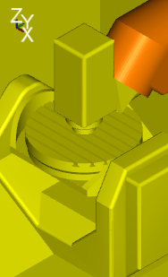
In this example, the B axis of the Tilt Table is edited using the slider. Note that the selected axis is highlighted in the Machine Tree and in the display.
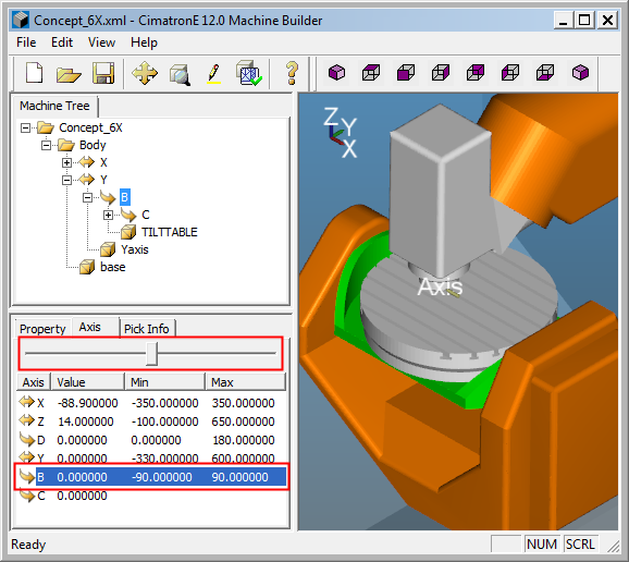
The result is displayed in the tab table and also the display. In this example, the Tilt Table is tilted.
Pick Info tab
The Pick Info tab appears after you double click on an object in the graphic window. This tab displays information relevant to the selected item. This information cannot be manipulated.