NC Setup  / Edit NC Setup Parameters

Access: Open this function from one of the following locations:
NC Setup:
-
Select NC Process > Process > NC Setup from the menu bar.
-
Click the
button in the NC Guide Toolbar. -
Right-click in the Process Manager, or anywhere in the graphics window when no procedure is active, and select New > NC Setup from the popup menu.
Edit NC Setup:
-
Select NC Edit > Change Parameters > Edit NC Setup Parameters from the menu bar.
-
Right-click in the Process Manager, or anywhere in the graphics window when no procedure is active, and select Edit > Edit NC Setup Parameters from the popup menu.
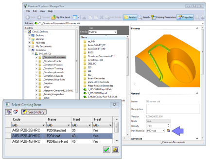
The NC Setup enables you to predefine multiple project-related options in a single place. The NC Setup contains the general data associated with a project, such as the part material, part geometry, machining orientations, fixtures, initial stock, machine name, and post processor. The data defined in the NC Setup is later used as the default for various NC operations. For example, the defined part material is used to set different machining parameters in the cutter definition. The NC Setup parameters can be edited as required.
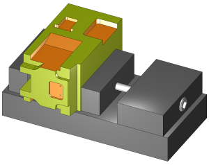
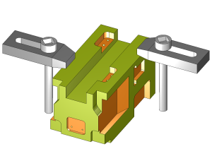
The images below show two setups of the same part – each setup with its own orientation and fixture.
|
|
|
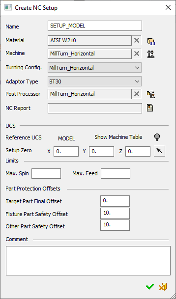
The Create NC Setup dialog, or the Modify NC Setup dialog, is displayed depending on the type of operation (the dialogs have the same layout but the Create NC Setup is initially displayed empty and the Modify NC Setup contains previously defined content):
|
|
The NC Setup is defined as a special 'toolpath (TP) folder' which contains data in the folder itself and also Part and Stock procedures. Milling procedures can be created or copied to this NC-Setup folder. The NC Setup TP folder affects all subsequent procedures in other TP folders, until it is modified in a subsequent NC Setup TP folder. TP folders can be defined as 'NC-Setup' when these folders are created. Initially, the NC Setup contains blank data. The NC Setup can be copied with or without its Stock and Part procedures. It is also possible to save and load the NC Setup to a template, view and edit an existing NC Setup, delete the NC Setup, or report the NC Setup dialog parameter values in the NC Report. Moving the NC Setup up or down in the Process Manager or deleting them affects related procedures with the new order. However, NC-Reports and Posts that were done before moving the NC Setup are not effected. This affects related procedures in the same way as moving or deleting Stock procedures. For more, see NC Setup Parameters below. |
NC Setup Parameters
In the Create/Modify NC Setup dialog the following data my be defined:
|
Name |
The setup name has an automatic default value given to it (in the same way it is given to a TP folder when it is created or duplicated). The default text of the name is SETUP_<active UCS name>_<counter number>. The first setup name does not have a counter number as shown in the above dialog. This parameter field is editable. In the Process Manager, the displayed Setup name has (# P) appended to it in the same way it is for a TP folder (where the # represents the number of Stock and Part procedures within the Setup folder). |
||||||
|
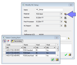
Material |
This field displays the material name which is selected by using the following button adjacent to the field:
|
||||||
|
Machine |
This field displays the name of the machine which is selected for the machining process. Set the required machine by using the following buttons adjacent to the field:
|
||||||
|
Turning Config. |
For turning (lathe) cutters and procedures, a Machine Definition Document (MDD file) is required. The MDD is created during the Machine Definition process. The Turning Config. parameter associates a MDD file with the Machine type currently specified in the NC Setup dialog. The MDD is a prerequisite for enabling turning operations. If no MDD is selected, turning cutters and operations are prohibited. The Turning Config. parameter is only displayed if you have a license for turning operations. Select the required MDD configuration from the Turning Config. dropdown list. The available values for the Turning Machine are the available MDD files for the selected machine. Notes:
The MDD files are saved in the same folder that contains the machine
definition XML file. The system retains the relation between a machine
and its MDDs by keeping them in the same folder. MDD files may either
be system supplied or user-defined.
The Machine Definition library of machine models are stored in XML files in the following folder:
...\ProgramData\Cimatron\Cimatron\2026.0\Data\Nc\MachineWorks
|
||||||
|
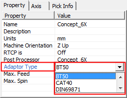
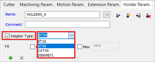
Adaptor Type |
The Adaptor Type can be selected from a dropdown list. This parameter can be set in the NC Setup, Machine Definition, and also in the Holder Parameters tab of the Cutters & Holders dialog. This list of adaptors is the same for both locations and is saved in the following folder: A warning is issued if the adaptor type of a holder is not identical to the adaptor type of a machine defined in the NC-Setup. The adaptor settings are compared and a warning is issued (if required) when the following occurs:
If a warning message is displayed, you can either ignore and continue or cancel the selection of the holder. In the latter case, either modify the adaptor for the selected holder or select another holder with a suitable adaptor. When selecting a holder from the Holder Library, you can filter the holders by their adaptor type.
|
||||||
|
Post Processor |
This field displays the name of the post processor that is selected for the machining process by using the following button adjacent to the field:
Note: When a machine is selected or modified and the Post Process parameter is empty, the post processor selected for the machine becomes the Post Process parameter value. |
||||||
|
NC Report |
This field displays the NC Report name, which is selected by using the following button adjacent to the field:
The default location for the NC Setup Report is in the following folder:
...\Users\<username>\AppData\Local\Temp |
||||||
|
Reference UCS |
Define the Reference UCS on which the current operation is to be based from a dropdown list of all the UCSs in the current ELT file. This Reference UCS enables you to define a different UCS as required; for example, when a different clamping situation is necessary, typically "Machining from TOP" and "Machining from BOTTOM". In the example below, the orange surface will be machined from above and the green area from the side. Because it is machined from another orientation, the green surface toolpath has different motion limits, which are based on its own separate UCS.
The Reference UCS is also important in the posting process where it defines the reference point and reference axes direction for the whole posting process. All other UCS's and tool points are defined relative to the Reference UCS. For additional information, see GPP2:
Reference UCS and the posting process.
The Reference UCS is also used by the Setup
Zero.
The default value is the active UCS. |
||||||
|
Setup Zero |
The numbers displayed here represent the position of the part (to be machined) on the machining center, relative to a predefined UCS. You can modify the offset values to adjust the part location within the machine envelope, enabling optimal use of the available space. Define the XYZ machine zero in the coordinate system, either by directly entering the XYZ coordinates or by using the adjacent The coordinates are passed to the Post Processor in the BEGINNING OF TAPE block (X_MACH, Y_MACH, Z_MACH).
This definition is needed for Machining Simulation, but also affects the actual G-Code if being used by the specific post processor. Modifying the Reference UCS at any point (or switching between a GPP post processor to a GPP2 post processor) does not affect the numbers. Once calculated (or keyed in), they stay "as is". For GPP2, setting the displayed numbers at (0,0,0) effectively tells GPP2 to ignore them (since it means that the machine zero point is at the REF UCS zero point). This is equivalent to setting M5_USE_MACH (5X machine definition variable) to FALSE inside the post processor. |
||||||
|
Show Machine Table |
Show or hide the machine table in the display. |
||||||
|
Max. Spin |
Enter Spin and Feed limits by setting their maximum values. If new procedure settings exceed these values, a warning message is displayed. If any or both of these maximum values are set (not blank), the following occurs: When a procedure is created from a template or copied into NC Setup, the system checks the spin and feed of the procedure and issues a warning if any of these values exceed the maximum. When a procedure is created manually, the spin and the feed values are automatically set to the maximum defined. If these values are exceeded, a warning message is displayed.
|
||||||
|
Part Protection Offsets |
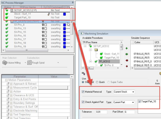
Set the default part protection offsets. These offsets are applied to surfaces during calculation and or simulation. This enables you to save time in Machining Simulation setup by keeping your stock and part settings under the NC Setup in the Procedure Manager (and not inside the toolpaths). It automatically checks ON the simulation screen boxes for Material Removal and Check Against Part, eliminating the need to manually check these boxes.
|
||||||
|
Comment |
Enter a comment, if required. This parameter field is editable. |


Notes:
-
When creating a new NC Setup folder:
-
-
The default value for the Reference UCS is the active UCS.
-
The default value Setup Zero X,Y,Z coordinates is 0,0,0.
-
-
Reference UCS: Only one UCS can be defined as the Reference UCS. This can be modified from the following locations. Once modified in any of these locations, the new UCS is shown in all the locations.
When running the Post Processor and NC Report, the default Reference UCS is that of the relevant NC Setup (if more than one NC Setup is involved, then the first Reference UCS is used).
-
Setup Zero: Only one point can be defined as the Setup Zero. This can be modified from the following locations. Once modified in any of these locations, the new Setup Zero is shown in all the locations:
-
Operations from different NC Setups: Warning messages can be displayed when operations (such as Post Processing, NC Reporting, Simulation, and procedure Transformation) from different NC Setups are invoked. The display of these messages, which require a confirmation to either continue or cancel the operation, is controlled from the Preferences (Tools > Preferences > NC > General Preferences).