|
|
Table of Ejectors  : Options and Results


Access: Open this function from one of the following locations:
-
Select Mold Design > Ejection > Table of Ejectors from the menu bar.
-
Select Ejection > Table of Ejectors from the Mold Design Guide Toolbar.
Create a Table of Ejectors. The function automatically selects known ejection devices, numbers them, and creates corresponding numbers as engravable text on the pins and their holes in the ejector retainer plate. Several options allow you to control the numbering scheme as well as the size and style of the text. In addition, the function also outputs a full table of the ejectors to an Excel report, with information such as the ejector diameter, length, XY location, and BOM ID number.
Required Step 1 
Select the required ejectors. By default, the system selects all of the ejectors that are under the active assembly. You can unselect ejectors, as required. Instances of selected ejectors are selected or unselected together.
|
Example mold before invoking the Table of Ejectors function: |
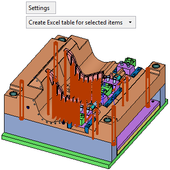
The same mold after invoking the function; all the ejectors are automatically selected: |
|
|
|
|
Settings |
Press the Settings button to display the Table of Ejectors - Settings dialog, see below. |
|
Create Excel Table for all selected items |
This is a dropdown list that enables you to control whether or not to create an Excel table of ejectors upon exiting the function. The following options are available in the dropdown list: Don't Create Excel Table Create Excel Table for selected items Create Excel Table for all numbered items
|
Settings
Display the Table of Ejectors - Settings dialog.
|
|
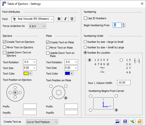
The following parameters are displayed:
|
Font Attributes |
Set the Font type, bold, italics and underline. |
||||
|
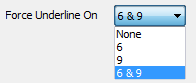
Force Underline On |
Force Underline On enables you
to put an underline under certain numbers even if the Underline option
is turned off. The dropdown options are: |
||||
|
|
|||||
|
Ejectors/Plates |
Define whether to create text on the ejectors/plates and if so, set the text display parameters. In the case of ejectors and sleeves, when sleeves are independent parts,
the Table of Ejectors tool knows to find ejectors and sleeves that go
through the same hole and make sure they get the same number. However,
when sleeves are all instances of the same part, the numbering mechanism
is adjusted to give a unique number to all sleeves that are different
than the one given to the ejectors.
An image displaying this feature is shown in the example images below. |
||||
|
Create Text on Ejectors/Plates |
This option controls text creation on ejectors and/or plates. If this option is selected (by default it is ON |
||||
|
Mirror Text on Ejectors/Plates |
Display the text as mirrored text. This is useful if you are viewing the mold from the bottom. |
||||
|
Upside Down Text on Ejectors/Plates |
Display all text upside down. |
||||
|
Text Rotation |
Rotate all text by the entered degree amount. Either enter the degree amount in the field (from -360° to +360°), or select it from the dropdown list. |
||||
|
Text Size |
Set the required font size in the text. Default = 5 |
||||
|
Text Color |
Select the color of the displayed text. |
||||
|
Text Position on Ejectors/Plates |
Select the appropriate radio button to position the text on the component, when looking from the top view of the mold. For Ejectors, the default position is the center of the ejector. When positioning text outside of the center of an ejector (where a sleeve will have a hole), it will be placed close to the edge of the base of the ejector. |
||||
|
Prefix/Postfix |
Add a prefix and/or postfix for ejectors and/or plates. These pieces of text are added before or after the 'main' text respectively. |
||||
|
|
|||||
|
Create Text as |
Text, including prefix and postfix text, can be created as standard wireframe Curve Text or as PMI Curve Text. Select the required option from the dropdown list. |
||||
|
Curve Text Feature |
Create a wireframe (curves) out of text. Create and position wireframe text (arcs & lines only) from text defined in any language, font, or according to specific parameters. The result is a Text feature.
This is the default option. |
||||
|
Curve Text PMI |
Create PMI Text that can be used as a curve. Create and position PMI text from text defined in any language, font, or according to specific parameters. The result is an annotation that behaves as geometry when exported to NC, Drafting, or external files. |
||||
|
|
|||||
|
Numbering |
|||||
|
Use ID Numbers |
For the ejector numbering, use either the numbers created by the Table of Ejectors function or use the ID Numbers of the BOM. When this checkbox is marked When this checkbox is OFF |
||||
|
Begin Numbering From |
Set the number from which to start numbering the first ejector. |
||||
|
|
|||||
|
Numbering Order |
The Numbering Order section is available for editing if the Use ID Numbers checkbox is OFF (the system uses the numbers created by the Table of Ejectors function). |
||||
|
Number by size - Large to Small |
Renumber by size from large to small or small to large. The sorting is done first by diameter, then by length, and then by the first ordering position. If either of the Number by Size options is selected, the Numbering by Location options are unavailable. |
||||
|
Number by size - Small to Large |
|||||
|
Numbering by Location |
Select the required radio button to define whether to number rows and then columns (this is the default), or columns and then rows. When this option is selected, the following options are also available:
|
||||
|
|
|
||||
| In Edit mode, the following parameter appears below the Settings button: | |||||
|
|
|
||||
|
Renumber Ejectors / Don't Renumber Ejectors |
This is a toggle option which appears only in edit mode. |
||||
|
Renumber Ejectors |
Renumber all selected ejectors. |
||||
|
Don't Renumber Ejectors |
Ejectors that already have a number will not get a new one. Only those that don’t have a number will get a new number, starting at the first number after the last used number (or a higher number if so defined in the settings). |
||||


The following approval options are available in the dialog:
|
|
Restore Default: Reset all values and settings to the system defaults. |
|
|
Save as Default: Save the current settings as the default. These default settings will be used whenever this operation is re-invoked. |
|
|
OK: Accept the changes, perform the operation, and close the current dialog/task. The last used values of all the parameters are kept for the current file. |
|
|
Cancel: Cancel all changes and close the dialog/task without saving the settings. |
Optional Step 1 
Manually select a target plate face upon which all plate text will be positioned.
By default, the plate face is selected automatically during Step 1. This optional step enables you to manually select the plate face.
A toggle option Select Plate Face Manually / Select Plate Face Automatically is displayed. The Manual mode is the default for this optional step. If you switch to Automatic, the system returns to the Step 1 stage.
Press OK ![]() or Apply
or Apply ![]() in the Feature Guide to complete the function.
in the Feature Guide to complete the function.
Example Excel Table Result
When OK ![]() is pressed, and if one of the option Create Excel Table has been selected (see above), the system displays the Save As dialog enabling you to save the .XLSX file containing the table of ejectors. The default file name is Table of Ejectors.XLSX and is saved in the same folder as the assembly. The table displays the information shown in the example table below:
is pressed, and if one of the option Create Excel Table has been selected (see above), the system displays the Save As dialog enabling you to save the .XLSX file containing the table of ejectors. The default file name is Table of Ejectors.XLSX and is saved in the same folder as the assembly. The table displays the information shown in the example table below:
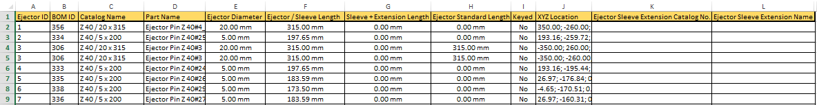
This table shows, among other data, the following columns:
|
Ejector / Sleeve Length |
The length of the sleeve itself. |
|
Sleeve+Extension Length |
This shows the combined length of the sleeve and the extension. |
|
Ejector Standard Length |
The original (catalog) length of the ejector. |
|
Ejector Sleeve Extension Catalog No. |
The extension catalog number, if it exists. |
|
Ejector Sleeve Extension Catalog Name |
The extension name, if it exists. |
Note: When there is more than one ejector sleeve going through the same hole:
-
The lower one is considered as the Ejector Sleeve Extension.
-
Only the lower one gets a plate number.
-
Two rows are displayed in the Excel table, one for the ejector and one for the ejector sleeve.
Example Ejector/Plate Result
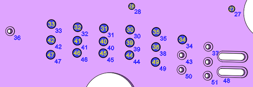
In the case of ejectors and sleeves, when sleeves are independent parts, the Table of Ejectors tool knows to find ejectors and sleeves that go through the same hole and make sure they get the same number. However, when sleeves are all instances of the same part, the numbering mechanism is adjusted to give a unique number to all sleeves that are different than the one given to the ejectors.
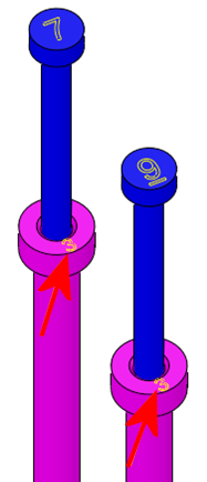
Below is an example of ejectors and their holes with corresponding numbers, and also an example of text on sleeves that are instances of the same part.
|
|
|
|
Example showing the ejectors and their holes with corresponding numbers. Note that the numbering positions are as defined by default - yellow text at the center of the ejectors and blue text at the bottom right of plate holes |
Example of text on sleeves that are instances of the same part. Note that the numbering on the sleeves is different to those of the ejectors |
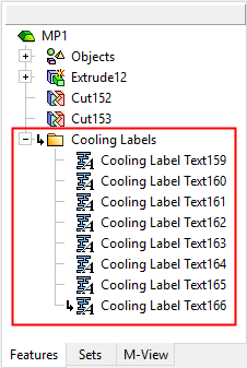
When OK ![]() or Apply
or Apply ![]() is pressed in the Feature Guide to complete the function, the Table of Ejectors feature will appear in the Feature Tree as follows:
is pressed in the Feature Guide to complete the function, the Table of Ejectors feature will appear in the Feature Tree as follows:
|
|
|
|