![]()
Toolpaths: Create 
![]()
![]()
Access: Open this function from one of the following locations:
-
Select NC Process > Process > Toolpath from the menu bar.
-
Click the Toolpath button
from the NC Guide Toolbar. -
Right-click in the Process Manager, or anywhere in the graphics window when no procedure is active, and select New > Toolpath from the popup menu.
Create a Toolpath. A Toolpath is a sequence of one or more machining Procedures, performed in a given set of milling axes.
The maximum number of toolpath folders in an NC file is 2000.
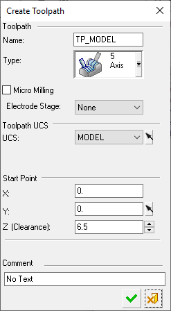
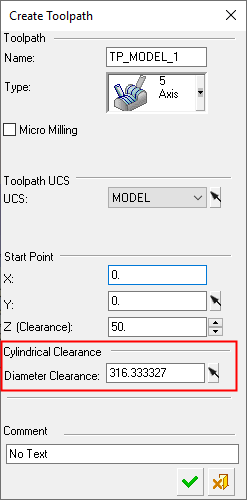
The Create Toolpath dialog is displayed. If a license for turning operations exists and a Machine Definition Document (MDD file) is defined in the NC Setup, a Cylindrical Clearance parameter is displayed.
|
|
|
Creating a toolpath
-
OpenOpen the Toolpath function.
-
In the displayed Create Toolpath dialog, set the appropriate parameters (see below).
-
Click OKOK
 when complete to continue. The toolpath now appears in the Process Manager.
-
You can modify the toolpath at any time.
-
You are now ready to create procedures for the toolpath.
Note: For an ASCII file containing details of the toolpath and all procedures it contains, select NC-Utilities > TP List.
-
Create Toolpath Parameters
|
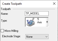
Name |
The toolpath name. Assign a toolpath name or accept the default name. |
||||||||
|
Type |
Select the toolpath type from the dropdown list.
|
||||||||
|
Micro Milling |
Decide if the toolpath is to be a Micro Milling or a standard toolpath. If a Micro Milling toolpath is created, it cannot be changed into a standard toolpath, and vice versa. |
||||||||
|
Electrode Stage |
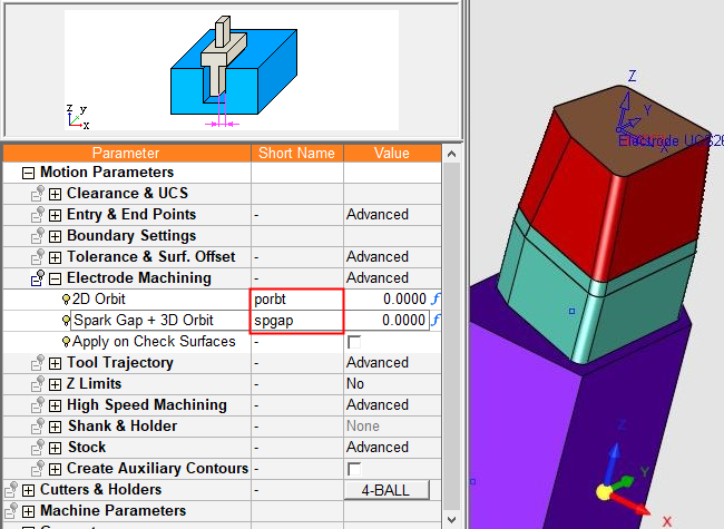
A dropdown list of the various electrode burning stages set in the EDM Setup. The default option is None. This parameter is only relevant when electrode machining (after exporting the electrode to NC) and is used with the electrode burning parameters. This parameter is displayed if the following conditions are met: Burning stage parameter values are set in the EDM Setup. In NC, the Load Model file is an electrode file. The NC file is created by Export to NC from: a. An electrode file. b. An open component electrode in an electrode assembly. In the NC Preferences > Procedure Parameter Defaults, select YES for the option Automatically Update Electrode Burning Parameters in NC Procedures. The electrode parameter values set in the EDM Setup are automatically updated in the NC procedure if: A value other than None is selected in the dropdown list. if the Electrode Machining parameter branch is set to Automatic. If None is selected in the dropdown list, the Automatic option is not available for the NC Electrode Machining parameter branch and the parameter values for this branch are not set automatically. Note: When exporting an electrode to NC, the overburn offset values for the electrode are automatically imported. You can find these values preset in any procedure that has the Electrode Machining parameter set to Automatic. These values are also loaded into the NC short name variables spgap and porbt, which means that they can be referenced in other formulas (e.g., step-overs, cutter size). This can be especially useful for electrode machining templates, ensuring a consistent result regardless of the overburn design of the electrode.
|
|
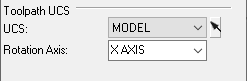
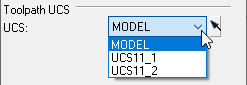
UCS |
Choose the toolpath orientation by selecting a UCS. You can select a UCS from the dropdown list or by pressing the yellow arrow next to the dropdown list and picking the required UCS in the graphic area. |
|
Rotation Axis |
If 4-Axis milling was chosen, enter the rotation axis for the cutter (X, Y, or Z axis). |
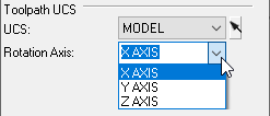
If a license for turning operations exists and a Machine Definition Document (MDD file) is defined in the NC Setup, a Cylindrical Clearance parameter is displayed.
|
|
|
|
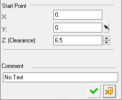
Start Point |
Assign X and Y values for the toolpath start point. These coordinates are in the UCS you selected in the previous step. Examples: Press the yellow arrow next to the Y value fieldPress the yellow arrow next to the Y value field
Pick the required UCS in the graphic areaPick the required UCS in the graphic area
The start point coordinates are changedThe start point coordinates are changed
|
|
Z Clearance |
Assign the Clearance Plane Z Value. This is the level from which the cutter starts its movements. The level is shown in the display. Examples: Original Clearance PlaneOriginal Clearance Plane
New Clearance PlaneNew Clearance Plane
|
|
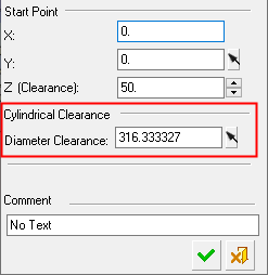
Cylindrical Clearance |
Set a cylindrical clearance value for turning (lathe) operations. The may be set for a Diameter Clearance or Radius Clearance value, depending on the Turning Defaults preference setting. A Solid cylinder is displayed. The default value is calculated by the maximum distance of all points in the geometry from the Z-axis plus the Default Clear Plane value from the preferences. The Cylindrical Clearance parameter is only displayed if a license for turning operations exists and a Machine Definition Document (MDD file) is defined in the NC Setup. A solid cylindrical clearance is displayed around the stock at the Diameter/Radius Clearance distance.
|
|
Comment |
Enter a comment to describe the toolpath. |