|
|
Turning Insert Specs 

Access: Open this function from one of the following locations:
In the Turning Cutters dialog:
-
Select the New Cutter icon
 .
. -
Select the Edit Selected Cutter icon
 .
. -
Double-click a cutter row to edit the selected cutter.
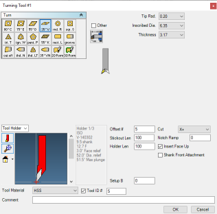
In the Turning Cutter Definition dialog, define the insert specification parameters, offset, and tool holder orientation of the selected insert type.
Example dialogExample dialog
|
|
Insert Parameters
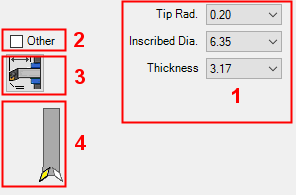
These parameters define the dimensions of the currently selected insert type.
The parameters that are displayed correspond to the selected insert type. Each of the dropdown lists will limit the selections available in the dropdown lists that follow it. For example, selecting a Tip Radius will limit the number of available Inscribed Circles and Thicknesses. Selecting an IC will further limit the number of Thicknesses available. These settings will limit the number of available tool holders and boring bars in the holder diagram. If no tool holders or boring bars are available, the Other choice will be automatically selected.
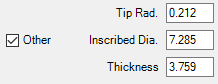
When the Other checkbox situated next to the tool specifications is selected, you can enter any tool specifications you want.
|
|
Tip Length Tip Width Tip Radius Insert Width Face Angle Inscribed Diameter |
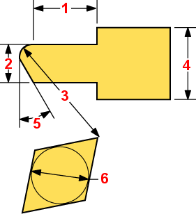
The parameters that are displayed, depend on the type of insert selected. The following is a list of the available parameters displayed alphabetically:
|
Deflection Compensation |
When this checkbox is marked |
|
Face Angle |
The angle of the insert's cutting face. |
|
Full Radius |
When this checkbox is marked |
|
Insert Type |
The type of thread the insert will cut. |
|
Insert Width |
The width of the insert. |
|
IC |
The inscribed diameter of the insert for triangular thread tools. This is the diameter of a circle that fits exactly within the boundaries of the insert. |
|
Inscribed Diameter |
The inscribed circle of the insert (the diameter of the circle inside the insert). |
|
Size |
The IC size of the rectangle. If the Other button is turned on with this type of insert, then the length and width of the insert need to be entered instead of the size. |
|
Style |
The thread style of the insert. |
|
Thickness |
The thickness of the insert in the Y direction. |
|
Tip Length |
The length of the insert tip. |
|
Tip Radius |
The radius of the insert tip. |
|
Tip Width |
The width of the insert tip. |
|
TPI |
The threads per inch specified by the blueprint. |
|
Width |
The width of the insert. |

Other
The Other option enables you to define any parameter values without having to select a set value from a dropdown list. This option may be used if the required value(s) are not available in the dropdown lists.
|
When this checkbox is OFF |
When this checkbox is marked |
|
|
|


Lathe Tool Offset Data
|
|
This button enables you to define the Tool Setup data. Click this button to display the Tool Setup Data dialog. This dialog is used to set distance between the toolgroup (tool attachment position) and the tool tip. |

The Tool Setup Data dialog is displayed.
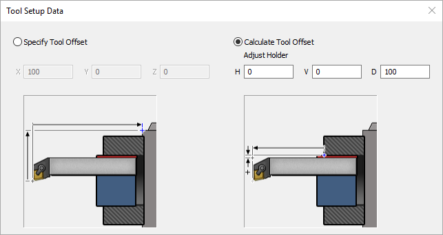
Specify Tool Offset
This is used to specify the actual distance measured along all 3 axes. Note that specifying values here can affect values in the output code based on tool change positions.
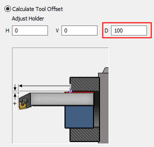
Calculate Tool Offset
This will calculate this distance using the shift from the tool holder and the tool shank, plus additional shifts in each axis that you provide here.
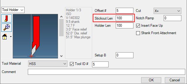
Note: The shift along the depth axis of the tool is equivalent to the stickout length for a turning tool.
|
|
|
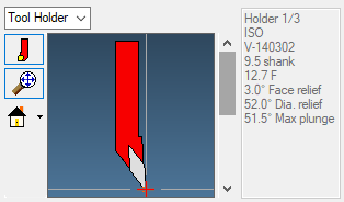
Tool Holder Orientation
|
|
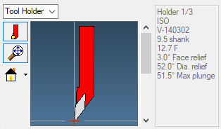
This image is used to specify the orientation of the insert in the tool holder or boring bar. The highlighted insert signifies the current orientation. |

To change the current orientation, select another insert orientation.
|
|
|


Changing the information will not affect the availability of other items in the dialog, but it will change the orientation of the Holder image.
|
|
|
|
|
|
|