|
|
Turning Tool Holder Definition 

Access: Open this function from one of the following locations:
In the Turning Cutters dialog:
-
Select the New Cutter icon
 .
. -
Select the Edit Selected Cutter icon
 .
. -
Double-click a cutter row to edit the selected cutter.
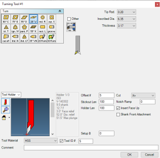
In the Turning Cutter Definition dialog, define the tool holder data of the selected insert type.
Example dialogExample dialog
|
|
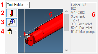
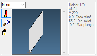
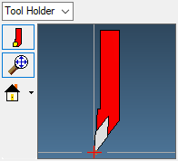
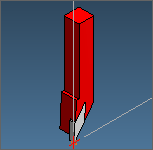
The tool display provides information about the touch off and type of holder or boring bar that is used for the insert. Holders can be chosen by using the scroll bar to the right of the tool/holder preview window. The text to the right of the scroll bar displays the tool/holder specifications, which provide detailed information about the insert angle and holder type.
The selection of insert and tool holder affects the toolpaths created using this tool. The system uses the current selections when constructing a toolpath to prevent tool interference. Therefore, insert and tool holder selections directly affect the machining of the part.
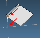
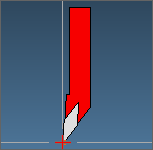
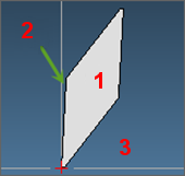
The red plus sign at the end of the insert indicates the location of the current touch-off point. Most Lathe tools have a choice of touch-off points. Simply click the required plus sign. Choosing an alternative touch-of point will affect the toolpath and the output code.
|
Diamond tool |
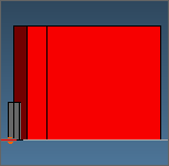
Thread tool |
|
|
|
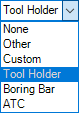
Tool Holder dropdown list
Depending on the tool selected and Machine type used. The following holder options are available in the dropdown list:
|
None |
For certain lathes which have no rotary axes apart from a C axis, the option None is available. In this case Face and Diameter relief fields are provided. If None is selected, no holder will be displayed on the preview pane.
|
||
|
Other |
This is the default option. Use this option if there are no tool holders or boring bars available in the database for the selected insert and you do not wish to define a custom holder shape. Dimensions of the tool holder can be defined by clicking the adjacent Edit button (displayed when the Other option is selected). The Other Holder dialog is displayed.
|
||
|
Custom |
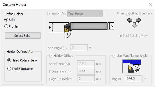
This enables you to define a Tool Holder, Boring Bar, or ATC Holder. You can choose either a Solid or a Profile to define the holder. The new holder is displayed in the preview window. Use the adjacent Edit button (displayed when the Custom option is selected) to change any of the settings. The Custom Holder dialog is displayed.
|
||
|
Tool Holder |
Displays the tool holders, boring bars and ATC holders available for the specified insert type and size, as well as the machine shank size. Use the scroll bar adjacent to the holder preview to scroll through the list of holders available in the chosen category. The selected holder information is displayed next to the scroll bar. The holder selection is used to determine the diameter relief and face relief angles. The Stickout Length must be entered. |
||
|
Boring Bar |
|||
|
ATC |
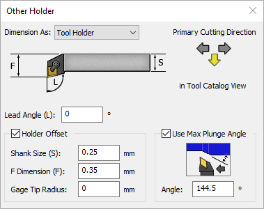
Custom / Other Holder dialog parameters
The parameters in the Custom Holder and Other Holder dialogs are very similar and are described below.
|
|
|
Parameters
|
Define Holder |
Define the custom holder parameters. |
||
|
Solid |
The Solid option allows you to use an existing solid to designate the tool holder. Click the Select Solid button to select the solid model of the holder. The custom holder is displayed in the preview window. |
||
|
Profile |
The Profile option allows you to utilize existing geometry to designate the tool holder. Click the Select Contour button to select the geometry profile of the holder. The custom holder is displayed in the preview window. |
||
|
Holder Defined At |
Specify the orientation of the holder, either at the Head Rotary Zero or at the Tool B Rotation. |
||
|
Dimension As |
Choose either Tool Holder, Boring Bar, or ATC Holder and specify the Primary Cutting Direction using the arrow keys, either West, South, or East. The default cutting direction is westward for boring bars and southward for tool holders. |
||
|
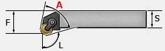
Lead Angle (L) |
This is the insert lead angle, as defined by 'L' in the dialog image.
|
||
|
Holder Offset |
When this checkbox is marked |
||
|
Shank Size (S) |
The shank size of the holder as defined by 'S' in the dialog image. |
||
|
F Dimension (F) |
The F dimension is from the tool tip to the back of the holder as defined by 'F' in the dialog image. With Boring Bars the F dimension is from the tool tip to the center of the Datum or Boring bar. |
||
|
Gage Tip Radius |
If an F dimension is used, in order to calculate it correctly, enter the Gage insert tip radius. |
||
|
Use Max Plunge Angle |
When this checkbox is marked |

Orientation and Positioning Notes:
Positioning and orientation of Lathe toolholders.
-
Orientation
Lathe custom solid tool holders may be positioned at either the cutting orientation specified in the tool dialog or at machine rotary zero. The orientation of the holder in the first part station's XY CS is preserved when the holder is applied. The only variation is whether the machine is at its zero position or has the second rotary axis rotated to the tool's setup angle. The insert is oriented in the first part station's ZX CS.
Lathe custom profile holders are positioned much like lathe custom solid holders, but as if they were going to cut in the current CS rather than in the first part station's ZX CS. -
Positioning
Custom holders are placed relative to the first part station's origin. For lathe tools, this means that the tool touchoff point and holder offsets are calculated from the origin.
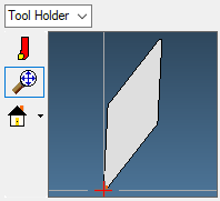
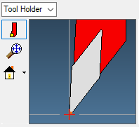
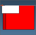
Show/Hide Holder in Preview 
Show or hide the holder in the preview window. A thin blue line is shown around the icon if the holder is displayed.
|
Show tool holder |
Hide tool holder |
|
|
|

Tool/Holder Zoom All 
Zoom the tool/holder to center and fill the preview window. This is useful if you have expanded the tool using the mouse.
A thin blue line is shown around the icon if the Zoom All is active (the preview image is zoomed to fit the preview window).
|
Preview zoomed |
Tool/Holder Zoom All |
|
|
|
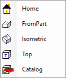
View dropdown 
Select a preset view to be displayed in the preview window. The Catalog option will display the tool holder as shown in the Other Holder dropdown option described above.
|
Home |
FromPart |
Isometric |
Top |
Catalog |
|
|
|
|
|
|
Tool/Holder Preview
The Tool/Holder preview is mouse-enabled. You can mouse-drag a rectangle to expand an area, turn the mouse wheel to zoom in or out, or hold down the wheel and move the mouse to change the view.
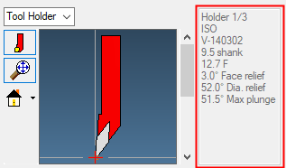
Holder Specification
The text to the right of the tool/holder preview window scroll bar displays the specifications of the selected tool/holder, which provide detailed information about the insert angle and holder type.
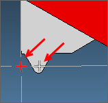
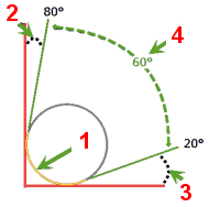
The Diameter Relief and Face Relief settings are calculated automatically from the defined Included Angle value (see above).
Diameter Relief: The Angle of the insert to the horizontal line (the angle the tip is approaching). Changing this affects the Face Relief because the sum of the three angles (Insert angle, Face Relief angle and Diameter Relief angle) must be 90 degrees.
- A Diameter Relief of 0 degrees places the insert edge on the part face.
- A positive Diameter Relief degree value moves the edge away from the part face.
- A negative Diameter Relief degree value moves the edge into the face.
Face Relief: The angle of the insert to the vertical line (the angle of the insert's approach). Changing this affects the Diameter Relief.
|
|
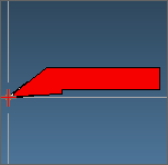
35° Insert 3° Face Relief 52° Diameter Relief |
|
|
Cutting Surface Face Relief Angle Diameter Relief Angle Included Angle |
|