|
|
Progressive Die Workflow
The Strip Part inCimatron is essential for the die design process. It is the mandatory first step in the design of any progressive die. It represents the process (or roadmap) for how the final part will be produced step-by-step within the die. This includes all the blanking, forming, piercing, and trimming operations.
The Cimatron processes involved in creating a Progressive Die are detailed below:
-
Run the Progressive Die Setup Wizard and browse for a master part (final product). Two masters can be handled in Progressive Die.
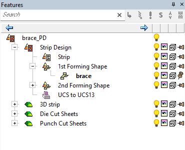
A default assembly tree with a predefined structure is created with two distinct environments - the Strip Application environment and the Forming Shape environment.
The Die Design module is used to create the blanking station layout as well as the layout of the part shapes in each stage of forming, piercing, or trimming that are required for the design. The Strip Layout is only a guide for the design. It is not used for the actual manufacture of the die components. The designer will often create a set of separate die cut sheet and punch cut sheet files. These files will contain the sheet surfaces that are to be used in the die block design process and in some cases, the machining of the blocks. By adding these few intermediate files, the designer can separate (and isolate) much of the intricate surfacing work to the sheet files keeping the files that contain the die blocks in the design cleaner, smaller, and less complex.
At the end of the Die Design process in Cimatron , the strip layout contains your final developed part outlines and all of the 3D forming shapes needed to create your design. These are sheet bodies with no thickness.
By convention, any component in a progressive die that has shape or will somehow contact the strip is called a Block. These start out as solid blocks of steel (usually) and are machined as necessary. In general terms, a solid object is created by extruding a 2D shape such as a square or rectangle. That extruded shape is then cut using the surfaces in the appropriate sheet file. Typically, the stamping plants may require these original sheet surfaces to be sent, along with the 3D die design.
These sheets can be used for machining if any work needs to be done on the tool. Cimatron automatically creates three files which are available for use if you follow this workflow.-
3D strip - The strip layout consists of sheet bodies with no thickness. This includes the Strip Part and all of the Forming Shapes. When the design is finalized, this final strip design can have a thickness applied to it to become a closed solid body. The 3D strip part can be used as the destination to copy the entire strip design and apply a thickness.
-
Die Cut Sheets - The normal starting point when creating a shape is to extrude a square or rectangular block, then to cut that block to the 3D sheet surfaces to transfer the shape to the block. This file contains all the sheet surfaces to do the cutting. The strip design is imported into this folder using the File > Import > Import Geometry command and the block surfaces for each station are created as necessary. Generally, because there will be a significant amount of work performed in this stage, it is not efficient to maintain the file associations between the cut sheet files and the files that contain the blocks being cut. Many tooling firms require the original sheet surfaces be sent along with the 3D die design to enable them to perform any work that needs to be done on the tool. This file holds the sheets for the bottom half of the tool The normal starting point when creating a shape is to extrude a square or rectangular block, then to cut that block to the 3D sheet surfaces to transfer the shape to the block. This file contains all the sheet surfaces to do the cutting. Many tooling firms require the original sheet surfaces be sent along with the 3D die design to enable them to perform any work that needs to be done on the tool. This file holds the sheets for the bottom half of the tool.
-
Punch Cut Sheets- The strip design is also imported into this folder and the block for the top half of the tool is created. This folder will hold the design for the top half of each station in the progressive strip. It is usually created by importing the Die Cut Sheets (bottom sheets) and offsetting them by the appropriate amount to create the Punch (top) sheets.
If the Punch Cut Sheets are created first, the process is reversed. They will be imported into the Die Cut Sheet files and offset by the appropriate amount. It is a good practice to always start with either the top or bottom as the master surfaces. It will help avoid cyclic dependency issues by importing and offsetting the same faces in the same sets of files.
The Forming Shape Guide is displayed.
-
-
Use the Forming Shape environment to create intermediate shapes using the Forming Shape function. This includes creating the forming shapes that will be included in the strip. These forming shapes are generally copies of parts originating from the master die design file that are changed using the bend, unfold, unbend, and blanking operations.
-
If required, you can then add a second row of forming shapes using the Add 2nd Forming Row function. Added forming shapes may be mirrored or not.
-
You can now plan the piercing sequence (which holes will be created at which station) using the Piercing Design function (this function is also applicable for Transfer Die).
Piercing design is used for parts having arrays of holes that must be pierced in several consecutive operations, such as parts used in the electronic and computer industries.
-
You now switch to the Strip Application environment by clicking the Switch to Strip button at the bottom of the Forming Shape Guide.
-
Designing the Strip: this includes, nesting, designing the strip layout, dimensions, carrier, stations, punch/trim, and more.
-
Designing the die tool.
|